OWNER’S GUIDE ADVANCED REVERSE OSMOSIS WATER TREATMENT SYSTEMS
Please fill in the following information and retain for reference: Unit Model Number: _________________________________ Serial Number: _____________________________________ Date Purchased: ____________________________________ Date Installed: ______________________________________
INTRODUCTION Congratulations, on the purchase of your new Advanced Reverse Osmosis Water Treatment System. Treated with care and regular maintenance, your new system will provide many years of service delivering great tasting water to the tap. By now, you have probably already opened the box to survey the contents. Please take a few moments to review this manual before proceeding with the installation and use of the system.
GENERAL INFORMATION 1240 SERIES MODELS AND SYSTEM CONFIGURATIONS Number of Vessels Vessel 1 3VTFC25G 3 N/A 3VTFC50G 3 N/A Model Description Item # Table 1 (2) Vessel 2 Vessel 3 Dual Purpose Dual Purpose TFC Membrane (3) TFC Membrane Model Series 12401 1240101-## 1240102-## (1) (1) Model Series 12402 1240200-## 1240201-## 1240202-## 1240203-## (1) (1) (1) (1) 4VTFC09G 4 4VTFC25G 4 4VTFC50G 4 4VTFC75G 4 Sediment Filter Sediment Filter Sediment Filter Sediment Filter 1240301-## 1240
GENERAL INFORMATION This Owner’s Guide covers all components that may be included with a system. Information relating to any component that is NOT included with your system may be disregarded.
GENERAL INFORMATION PRODUCT WATER STORAGE TANKS PRODUCT WATER STORAGE TANKS - ALL SYSTEMS Item 1 2 3 Description Storage Tank Assembly, Polymer Storage Tank Assembly, Metal Ball Valve, 3/8” Figure 1.B: Product Water Storage Tanks. IV Part No.
INSTALLATION REQUIREMENTS READ THIS ENTIRE INSTALLATION AND SERVICE GUIDE BEFORE BEGINNING INSTALLATION The 1240 Series Reverse Osmosis (RO) Drinking Water Treatment Systems have been designed for ease of installation and serviceability and are constructed with the finest materials available. Using these instructions and paying close attention to the parameters outlined within "CONDITIONS FOR USE" detailed on Page II will ensure a successful installation.
SMARTAP® WATER QUALITY MONITOR ® WaterGroup’s 12403 Series Reverse Osmosis Systems incorporate a proven performance indicator. Our patented Smartap Water Quality Monitor uses dual probe LOGIC PULSE MEMORY technology to accurately indicate membrane performance. A splitsecond power pulse compares feed water Total Dissolved Solids (TDS) level with that of the product water. Then, by reversing the polarity of the electronic pulse, the probes are cleaned and kept free of chemical plating.
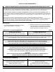
SADDLE-TAPPING VALVE INSTALLATION ON COPPER TUBE CAUTION: This saddle-tapping valve is not designed for installation on flex line tubing. NOTE: State, provincial and local plumbing codes may prohibit use of saddle-tapping valves. 1. 4. Connect source water feed tubing to valve body using compression fitting. CAUTION: If no shut off valve is installed under sink, close main water valve during this Installation. a. Slide nut and sleeve onto tubing (in that order).
DRAIN OUTLET ASSEMBLY INSTALLATION NOTE: State, provincial and local plumbing codes may prohibit use of saddle-tapping drain connections and may require use of an air gap. NOTE: Location and orientation of drain outlet assembly is vital to system performance. Vertical Drain Line: Locate drain hole on a straight length of drainpipe next to "P"/"S" trap between trap and sink.
PRODUCT WATER FAUCET SITE PREPARATION Refer to Faucet Installation Instructions (Page 6) for site location and mounting hole specifications. Primary considerations for site selection are convenience of use and an open area under sink. An existing 7/8” Sink Hole will also accommodate metal faucets with air-gap connections. Always check underside of selected location for obstructions. STAINLESS STEEL SINK PORCELAIN/ENAMEL OVER STEEL OR CAST IRON SINKS 1. 1.
METAL PRODUCT WATER FAUCET INSTALLATION AND SYSTEM CONNECTIONS Install faucet on flat surface at least 2" in diameter. Unused 1 1/4" hole is ideal. Steps unique to a specific configuration are so noted. All other steps are common to either configuration. New Faucet Installation Refer to Faucet Site Preparation, Page 5. 8. Replacement Faucet Installation Verify size of existing hole is 1 1/4". Connect loose ends of tubing as follows: a.
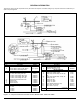
1 9 NON AIR GAP 4A 3 2 SINK OR COUNTER MATERIAL NON AIR GAP 4 5 AIR GAP AIR GAP ONLY 6 7 DRAIN LINE FROM AIR GAP TO DRAIN (3/8" RED TUBING) DRAIN LINE TO AIR GAP (1/4" RED TUBING) Description Chrome Plated Metal Non-Air Gap Faucet (USEPA Compliant, not available in California) Chrome Plated Metal Air Gap Faucet (USEPA Compliant, not available in California) FAUCET NIPPLE DRINKING WATER LINE FROM POST-FILTER TO FAUCET(3/8" BLUE TUBING) 8 Part No.
MODEL 12401 Item 1 2 3 4 5 6 7 8 9 10 11 12 13 14 15 16 17 Description Cover, 3-vessel Manifold † Screw, Inlet Valve Cover Cover, Inlet Valve "O" Ring, Inlet Valve Cover Shut Off Assembly Tubing, 1/4”, White * Flow Restrictor, 1240 Series, Red 25 GPD 50 GPD Tubing, 3/8”, Blue * Tubing, 3/8”, White * RO, 3V Manifold, Assembled ** Cartridge, Dual, Sediment/Carbon Filter Filter, Membrane Thin Film Composite 25 GPD, Yellow Casing Black Tape 50 GPD, Yellow Casing White Tape Cartridge, Carbon AES, 10 micron "
MODEL 12402 Item 1A 1B 2 3 4 5 6 7 8 9 10 11A 12 13 14 15 16 17 18 19 Description Cover, 4-vessel Manifold † Cover, 4-vessel Push Button Manifold † Screw, inlet Valve Cover Cover, Inlet Valve "O" Ring, Inlet Valve Cover Shut Off Assembly Tubing, 1/4”, White * Flow Restrictor, 1240 Series, Red 9 GPD 25 GPD 50 GPD 75 GPD Tubing, 3/8”, Blue * Tubing, 3/8”, White * RO, 4V Manifold, Assembled ** Cartridge, Sediment, 5 micron Filter, Membrane Thin Film Composite 9 GPD, Yellow Casing Red Tape 25 GPD, Yellow Ca
ACTIVATING THE SYSTEM CAUTION: Make sure all water supply lines, drain lines, and fittings are secure and free from leakage. 1. Open source water supply valve. Close product water faucet. Check for leakage. 8. Open product water faucet and let water flow until all air has been expelled from system. 2. Turn tank valve one-quarter turn counter- clockwise to open valve (handle should be in line with tubing as it enters connection). 9. Close product water faucet.
CLEANING, SANITIZING, AND CARTRIDGE REPLACEMENT PROCEDURE 1. Mix mild cleaning solution of dish soap and clean potable water in plastic bowl. 9. Rinse manifold/housings with clean potable water. 2. Empty storage tank and relieve system pressure. Verify tank valve is open. Close feed water supply valve and open product water faucet. 10. Inspect manifold and filter housing "O" ring groove area for damage (i.e., nicks or scratches). Replace damaged components.
CLEANING, SANITIZING, AND CARTRIDGE REPLACEMENT PROCEDURE 19. CAUTION: Do not remove protective plastic bag from replacement filter/membrane cartridges until so instructed. 28. Test battery connection by activating monitor. Press push button. If an indicator light illuminates, connection is good. Install "O" rings into filter housings. Open top of filter bag enough to expose filter cap and "O" ring grooves. Place a small amount of "O" ring lubricant on surface of each "O" ring. 29.
TROUBLESHOOTING INDICATORS AND COMMON SOLUTIONS Table 5 WATER VOLUME AND QUALITY Symptom Condition Action No product water. Water supply is turned OFF. Turn water ON. Not enough product water. Low water pressure. Water supply is blocked. Storage tank valve is closed. Storage tank is depleted. Check source water line pressure. Clear restriction. Open storage tank valve. Increase product water storage capacity and/or install membrane and flow restrictor with higher output rating.
LIMITED WARRANTY Subject to the conditions and limitations described below, WaterGroup warrants its Model 12401, 12402, and 12403 Series Reverse Osmosis Drinking Water Treatment Systems (excluding membrane, cartridge filters and battery), when installed in accordance with WaterGroup specifications, to be free from defects in materials and workmanship under normal use within ® the operating specifications for a period of two (2) years from the date of purchase.