
User Manual
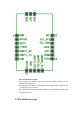
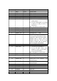
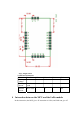
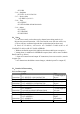
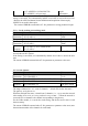

Pin number
Name Type Description
1 GND Power System GND
2 ANT RF Signal wire
3 GND Power System GND
4 GND Power System GND
5 GPIO4/PE7 I 1. For the external MCU to wake up
LoRa module
2. For the external MCU to let LoRa
to know it is ready to receive AT
instruction
More information see note below.
6 SWIM Debug IO Debug for simulator
7 nTRST I Reset ,low level signal effective.
8 UART1_RX I Serial port 1(3) ,receive
9 UART1_TX O Serial port 1(3), send
10 PWM/PD0 O For 9V battery power supply cases,
for low power consumption. Power is
supplied by LDO when the module is
dormant and by DCDC when the
module wakes up. This IO is high
output at module wake up and IO is
low level signal at dormanted.
11 GPIO3/PE6
O 1. To wake up external MCU。
2. To let the MCU know, LoRa
module is wake up and ready to
receive AT instruction ;
More information see note below.
12 GND Power System GND
13 VDD Power Power input 3.3V, maximum peak
current 150mA.
14 UART0_RX I Serial port 0 (2) , receive , AT
instruction port
15 UART0_TX O Serial port 0(2) , send , AT
instruction port
16 MISO/PF0 I SPI MISO
17 MOSI/PF1 O SPI MOSI
18 SCK/PF2 O SPI CLK
19 NSS/PF3 O SPI CS
20 IIC_SDA/PC0
IO IIC SDA