
Datasheet
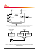
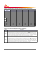
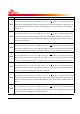
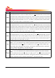

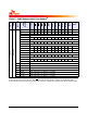
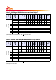
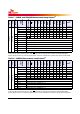
Table Of Contents
- Description
- Features
- Ordering Information
- Key Parameters
- Speed Grade
- Address Table
- Pin Descriptions
- Input/Output Functional Descriptions
- Pin Assignments
- Registering Clock Driver Specifications
- On DIMM Thermal Sensor
- Functional Block Diagram
- 4GB, 512Mx72 Module(1Rank of x8)
- 8GB, 1Gx72 Module(1Rank of x4) - page1
- 8GB, 1Gx72 Module(1Rank of x4) - page2
- 8GB, 1Gx72 Module(2Rank of x8) - page1
- 8GB, 1Gx72(2Rank of x8) - page2
- 16GB, 2Gx72 Module(2Rank of x4) - page1
- 16GB, 2Gx72 Module(2Rank of x4) - page2
- 16GB, 2Gx72 Module(2Rank of x4) - page3
- 32GB, 4Gx72 Module(4Rank of x4) - page1
- 32GB, 4Gx72 Module(4Rank of x4) - page2
- 32GB, 4Gx72 Module(4Rank of x4) - page3
- 32GB, 4Gx72 Module(4Rank of x4) - page4
- 32GB, 4Gx72 Module(4Rank of x4) - page5
- Absolute Maximum Ratings
- AC & DC Operating Conditions
- AC & DC Input Measurement Levels
- Vref Tolerances
- AC and DC Logic Input Levels for Differential Signals
- Differential signal definition
- Differential swing requirements for clock (CK - CK) and strobe (DQS-DQS)
- note : Rising input differential signal shall become equal to or greater than VIHdiff(ac) level and Falling input differential signal shall become equal to or less than VIL(ac) level.
- Single-ended requirements for differential signals
- Differential Input Cross Point Voltage
- Slew Rate Definitions for Single-Ended Input Signals
- Slew Rate Definitions for Differential Input Signals
- AC & DC Output Measurement Levels
- Overshoot and Undershoot Specifications
- Refresh parameters by device density
- Standard Speed Bins
- Environmental Parameters
- IDD and IDDQ Specification Parameters and Test Conditions
- IDD Specifications (Tcase: 0 to 95oC)
- Module Dimensions
Rev. 1.0 / May. 2014 57
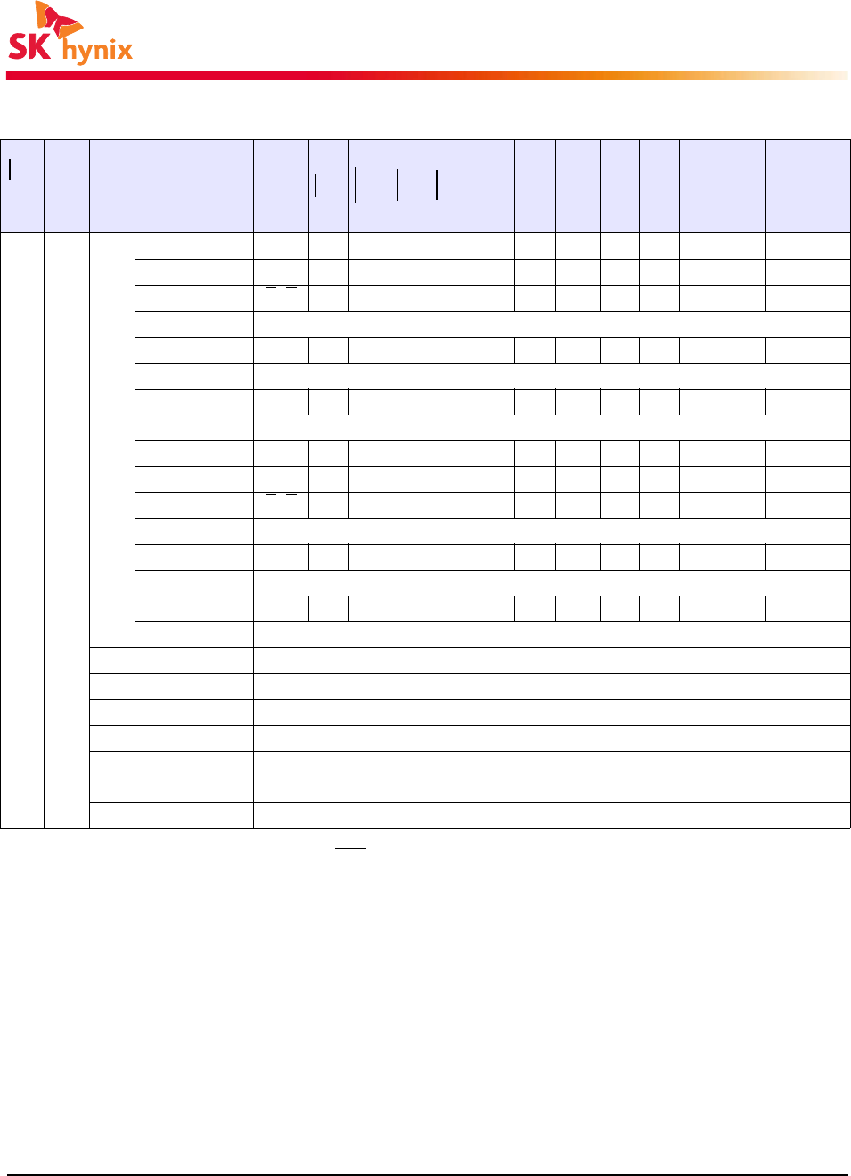
Table 4 - IDD1 Measurement-Loop Pattern
a)
a) DM must be driven LOW all the time. DQS, DQS are used according to RD Commands, otherwise MID-LEVEL.
b) Burst Sequence driven on each DQ signal by Read Command. Outside burst operation, DQ signals are MID_LEVEL.
CK, CK
CKE
Sub-Loop
Cycle
Number
Command
CS
RAS
CAS
WE
ODT
BA[2:0]
A[15:11]
A[10]
A[9:7]
A[6:3]
A[2:0]
Data
b)
toggling
Static High
0
0
ACT001100000000 -
1,2 D, D 1 0 0 0 0 0 00 0 0 0 0 -
3,4 D
, D 111100000000 -
... repeat pattern 1...4 until nRCD - 1, truncate if necessary
nRCD RD 0 1 0 1 0 0 00 0 0 0 0 00000000
... repeat pattern 1...4 until nRAS - 1, truncate if necessary
nRAS PRE001000000000 -
... repeat pattern 1...4 until nRC - 1, truncate if necessary
1*nRC+0 ACT 0 0 1 1 0 0 00 0 0 F 0 -
1*nRC+1,2 D, D 1 0 0 0 0 0 00 0 0 F 0 -
1*nRC+3,4 D
, D 1111000000F0 -
... repeat pattern nRC + 1,...4 until nRC + nRCE - 1, truncate if necessary
1*nRC+nRCD RD 0 1 0 1 0 0 00 0 0 F 0 00110011
... repeat pattern nRC + 1,...4 until nRC + nRAS - 1, truncate if necessary
1*nRC+nRAS PRE 0 0 1 0 0 0 00 0 0 F 0 -
... repeat pattern nRC + 1,...4 until *2 nRC - 1, truncate if necessary
1 2*nRC repeat Sub-Loop 0, use BA[2:0] = 1 instead
2 4*nRC repeat Sub-Loop 0, use BA[2:0] = 2 instead
3 6*nRC repeat Sub-Loop 0, use BA[2:0] = 3 instead
4 8*nRC repeat Sub-Loop 0, use BA[2:0] = 4 instead
5 10*nRC repeat Sub-Loop 0, use BA[2:0] = 5 instead
6 12*nRC repeat Sub-Loop 0, use BA[2:0] = 6 instead
7 14*nRC repeat Sub-Loop 0, use BA[2:0] = 7 instead