HM68X Digital Mobile Radio User Manual Hytera Communications Corporation Limited
Preface Welcome to the world of Hytera and thank you for purchasing this product. This manual includes a description of the functions and step-by-step procedures for use. To avoid bodily injury or property loss caused by incorrect operation, please carefully read the Safety Information Booklet before use.
Copyright Information Hytera is the trademark or registered trademark of Hytera Communications Corporation Limited (the Company) in the People's Republic of China (PRC) and/or other countries or areas. The Company retains the ownership of its trademarks and product names. All other trademarks and/or product names that may be used in this manual are properties of their respective owners. The product described in this manual may include the Company's computer programs stored in memory or other media.
Contents Documentation Information........................................................................................................................... 3 1. Packing List ................................................................................................................................................ 5 2. Product Overview ....................................................................................................................................... 6 2.1 Product Layout ............
9.1 Basic Settings ....................................................................................................................................... 19 9.1.1 Set Display ................................................................................................................................. 19 9.1.2 Set USB Path..............................................................................................................................19 9.1.3 Set Language .....................................
11.3.5 Enable BT Location ................................................................................................................... 30 11.4 One Touch Call/Menu ......................................................................................................................... 30 11.5 Roam .................................................................................................................................................. 31 11.6 Clarity Transmission ...............................
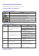
Documentation Information This section describes the conventions and revision history of this document. Documentation Conventions Instruction Conventions Icon Description Indicates information that can help you make better use of your product. Indicates references that can further describe the related topics. Indicates situations that could cause data loss or equipment damage. Indicates situations that could cause minor personal injury.
Document Version 00 Release Date September 2022 4 Description Initial release.
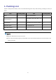
1. Packing List Unpack carefully and check that you have received the following items. If any item is missing or damaged, contact your dealer. Item Quantity (PCS) Radio 1 Mounting Bracket 1 Item Power Cord (with fuse) Quantity (PCS) 1 Self-tapping Screw (4.8 mm x 20 4 mm) Locking Knob 2 Self-tapping Screw (4 mm x 16 mm) 3 Palm Microphone 1 Documentation Kit 1 Microphone Hanger 1 / / Figures in this manual are only for reference.
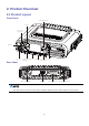
2. Product Overview 2.1 Product Layout Front Panel Channel/Navigation Key Volume Key Emer gency Key (pr ogr ammable) LED Indicator Aviation Por t Answer Key OK/Menu Key (progr ammable) Back/Z one Key End Key On- Off Key (programmable) Rear Panel RF Ant enna Connector Power Inlet Accessory Connector G PS Ant enna Connector The GPS antenna connector is only used to install the GNSS antennaon radios with the Location feature.
Palm Microphone 2.2 Programmable Keys You can request your dealer to program the Emergency key, Answer key, and End key as shortcuts to assignable radio features.
3. Installation 3.1 Precautions Before installation, read the following guidelines carefully: Before installation, ensure that the vehicle power supply has a negative ground withthe voltage of 13.6±15% V. Before installation, measure the length of screws protruding from the radio surface. During installation, drill the holes on the vehicle according to the screw length to avoid damaging the vehicle wires or other components. Use the antenna and power cord approved by the Company.
3.3 Parts No. Part Name No. Part Name 1 Radio 6 Self-tapping Screw (4 mm x 16 mm) 2 Locking Knobs 7 Microphone Hanger 3 Mounting Bracket 8 GNSS Antenna 4 Self-tapping Screw (4.
The RF antenna is optional. The GNSS antenna is a standard accessory for radios with the Location feature. 3.4 Procedure 1. 2. Install the radio. a. Select a location on the vehicle. b. Hold the mounting bracket to the location, and then mark the mounting holes. c. Drill holes at the mounting holes. d. Use the screws (4.8 mm x 20 mm) to secure the mounting bracket. e. Connect the RF antenna, GNSS antenna, and power cord to the radio. f.
4. Basic Operations 4.1 Turn On or Off the Radio To turn on the radio, connect the radio to power supply or long press the On-Offkey. To turn off the radio,long press the On-Off key. 4.2 Adjust Volume Toggle the Volume key up to increase the volume or down to decrease the volume. 4.3 Select a Zone On the home screen,press the Back/Zone key, toggle the Channel/Navigation key to select a zone, and then press theOK/Menukey. Press the preprogrammed Zone Up key or Zone Down key. 4.
5 Stattus Indications 5. 5 LCD 5.1 D Icons s Icon Radio Stattus T radio deetects no signnal. The M More bars inndicate strongger signal. T radio woorksin low poower mode. The T radio woorksin high power The p mode. A accessoryy is connecteed. An T GPS feaature is enablled, and validd positioning The g data has been received. T GPS feaature is enablled, but no vaalid positioning data has been receiveed. The T BT featuure is enabledd. The A BT devicee is connectedd.
Icon Radio Stattus T speaker is on. The T radio woorks in silentt mode. The T radio woorks in profille 1. The T radio woorks in profille 2. The T radio woorks in profille 3. The T There is/are (a) new message(s). T inbox is full. The T There is/are (a) missed caall(s). 5 LED 5.2 D Indica ators LED In ndicator Radio R Status s F Flashes greenn The radio r is beingg turned on. G Glows green The radio r is receiving. G Glows red The radio r is transmitting.
6. Call Services To ensure optimal voice quality on the receiving radio, keep the microphone 2.5 cm to 5 cm away from your mouth during speaking. 6.1 Group Call A group call is a call from an individual user to other group members. 6.1.1 Initiate a Group Call Through Preset Contact 1. On the home screen, toggle the Channel/Navigation key to select a digital channel. 2. Press and hold the PTT key. Through Contact List 1. Enter theContact interface.
Through Contact List 1. Enter theContactinterface. Press the preprogrammed Contact List or Favorite Contact List key. On the home screen, go to Menu>Contact. 2. Select a private contact. 3. Press and hold the PTT key. Through Call Logs 1. On the home screen, go to Menu>Call Logs. 2. Select aprivate call record. 3. Press and hold the PTT key. Through One Touch Call/Menu Press the preprogrammed One Touch Call/Menu key, and then press and hold the PTT key. 6.2.
2. Select an all call contact. 3. Press and hold the PTT key. Through One Touch Call/Menu Press the preprogrammed One Touch Call/Menu key, and then press and hold the PTT key. 6.3.2 Receive an All Call You can answer an all call without any operation. 6.3.3 End an All Call An all call ends when the caller releases the PTT key. 6.4 Analog Call An analog call is a call on the analog channel.
7. Message Services Messageallows you to send and receive text messages. 7.1 View aMessage Uponmessage reception, press the OK/Menu key. On the home screen, go to Menu>Message, select a message, and then press the OK/Menu key. 7.2 Delete a Message 1. On the home screen, go to Menu>Message. 2. Select a conversation. 3. Press the OK/Menu key. 4. Toggle the Channel/Navigationkey to select a message. 5.
8. Contacts To view the contact information, do the following: 1. On the home screen, go to Menu>Contactor press the preprogrammed Contact List key. 2. Select a contact.
9. Settings You can set radio parameters including Basic Settings, Call Settings, and Security Settings. 9.1 Basic Settings 9.1.1 Set Display On the home screen, go to Menu>Settings> Basic Settings>Display,and then set any of the following: Backlight The backlight illuminates the display and keypad. a. In the Display interface, selectBacklight. b. Toggle the Channel/Navigation key to select Off, On, or Timed. c. Press the OK/Menu key.
Option Port Description Operation path. Only Rear Port Only the accessory connector can be used as b. Select the USB path option. Press the preprogrammed USB Path Switch key. the USB path. 9.1.3 Set Language 1. On the home screen, go to Menu>Settings> Basic Settings>Language. 2. Toggle the Channel/Navigation key to select the display language. 3. Press the OK/Menu key. 9.1.4 Enable LED Indicator 1. On the home screen, go to Menu>Profiles>Setting>LED. 2. Press the OK/Menu key. 9.1.
If both the calling party and the called party enable the Auto Add Contacts and Send Alias features, the called party automatically adds the calling party to the contact list when receiving a call from the calling party. a. In the Talking Alias interface, select Auto Add Contacts. b. Press the OK/Menu key. 9.2.3 Enable Dual Slot Data Dual Slot Data improves transmission rate when the radio transmits packet data with other devices through dual slots.
Press the preprogrammed Scrambler/Encrypt key. When you enable Encryption, only the current channel is encrypted, and the channel remains to be encrypted after you switch the channel. 9.3.1.3 Select an Encryption Key 1. On the home screen, go to Menu>Settings>Security Settings>Encrypt>Key List. 2. Select an encrypt key. 3. Press the OK/Menu key twice. 9.3.
Alarm Type Description The Horn& Lights feature is enabled ordisabled based on the setting upon the last Alarm Re-Arm power-off. Non-Permanent Manual ReThe Horn & Lights feature must be enabledevery time upon power-on. Arm Permanent External Alarm The Horn & Lights feature is enabledwhenever the radio is powered on. On the home screen, go to Menu>Accessories>Horn & Lights, and then press the OK/Menu key. Press the preprogrammed Horn & Lights key. 9.3.
9.4.3 Set Audio Mode Audio Mode adds gain to audio signals at high, medium, and low frequency, thus optimize the audio quality. 1. On the home screen, go to Menu>Profiles>Setting>Audio Set>Audio mode. 2. Select an audio mode. 3. press the OK/Menu key. 9.4.4 Set MIC & SPK MIC & SPK allows you to select the microphone and speaker to transmit and receive voice. With the audio accessory connected, you can switch the audio paths. For details, see the following tables.
Option Description Operation microphone.
10. Profiles 10.1 Switch Profiles Profiles allows you to set the audio and alert tone of the radio for clear voice in various scenarios.The radio supports the following two profiles: General: applicable to common scenarios. Customized profiles: applicable to scenarios other than those in General. To switch profiles, do either of the following: On the home screen, go to Menu>Profiles, select a profile, and then press the OK/Menu key. Press the preprogrammed Profiles Switch key. 10.
11. Ra adio Featur F res 11.1 Scan 11.1.1 En nable Scan On the home screen, goo to Menu>S and th hen press the OK/Menu kkey. Scan>Scan On/Off, O p med Scan keyy. Press the preprogramm t the scan lisst preset for thhe current ch hannel. During the scanninng, the LCD displays d Thhe radio scans according to , and a thee LED indicaator flashes orrange slowly. W When detectingg activities on a channel, the radio stays on the chaannel and thee LED indicaator glows greeen.
This feature applies only to radios with GPS, BDS, or GLONASS. 11.2.1 Enable Positioning 1. On the home screen, go to Menu>Position>PositionOn/Off 2. Press the OK/Menu key. 11.2.2 View Position Local Position 1. On the home screen, go to the Menu>Position>Position View. 2. Press the OK/Menu key to view the position information of your radio (including longitude, latitude, speed, altitude, time, date, and the number of satellites). Contact Position 1.
2. Press the OK/Menu key. 3. SelectDisplay Type. 4. Select 16 Azimuth & Dist., Accur Azimuth & Dist., or Talker Location. 5. Press the OK/Menu key. 11.2.4 Enable GPS Report GPS Report allows the radio to report its location information to the control center. Press the preprogrammed GPS Report key, or you can consult your dealer to configure the GPS trigger, allowing the radio to automatically report the GPS data upon power-on/off, or according to the preset time or distance interval.
For details,refer to the accessory manual. 2. Search and connect to the BT device. 3. On the home screen, go to Menu>BT>Auto Search. 4. Select the BT device from the detected device list. 5. Press the OK/Menu key. After the radio is connected to the BT device, the LED indicator of the radio flashes blue every 1.5 seconds. 11.3.3 Switch BT Audio With the BT device connected, press the preprogrammed BT Audio Switch key to switch the audio output device between BT earpiece and the radio. 11.3.
Description Operation On a digital channel, you can do one of the following: Call/Menu key to initiate the service. Initiate a group, private, or all call. Send a quick text message or position message to a private or To initiate a call on a digital group contact. channel, press the One Touch Initiate an alert call, radio check, remote monitor, revive, or Call/Menu key, and then press and kill service. hold the PTT key. Switch to a function menu or realize a function. 11.
11.7 Ignition Sense Ignition Sense controls the radio on or off andthe PTT key enabled or disabled by starting or stopping yourvehicle engine. Four types of ignition sense are listed in the following table. The default type is Disable Ignition Off, and other types are enabled by your dealer. Type Description Operation pressthe On-Off key. Allows you to turn the radio on oroff by the Ignition or Switch engine or the On-Off key.
Auto Priority Interrupt Auto Priority Interrupt includes Emergency Priority Interrupt, Call Back Priority Interrupt, Message Priority Interrupt, Radio Disable Priority Interrupt, and All Call Priority Interrupt. You can interrupt an ongoing call by initiating an emergency call, all call, or sending a short message or the Radio Disable command. Contact your dealer to pre-configure the Auto Priority Interrupt feature. 11.
12. Em merge ency Servic S ce Em mergency Serrvice allows you y to seek help h from youur companion n or the contrrol center in case of emerrgency. You can c iniitiate an emerrgency call with w the higheest priority evven when you ur radio is trannsmitting or rreceiving. In emergency mode, m the raddio transmits at high poweer level by default. Accordding to the em mergency typee preset by yoour ncy types are listed in the following tab ble. deealer, the radio gives differrent indicatioons.
12.2 Receive an Emergency Call You can answer an emergency call without any operation. 12.3 End an Emergency Call Calling party Press the preprogrammed Emergency Off key. Turn off the radio. Called party Switch the channel. Turn off the radio. 12.4 Emergency Erase Data Emergency Erase Data allows the radio to erase encrypted data in case of emergency, so as to prevent unauthorized access. When erasing the data, the radio stops voice and data services and returns to the home screen.
13. Troubleshooting Phenomena Analysis Solution The radio cannot be turned The power cord may be unconnected. Connect the power cord properly . on. Make sure that call participants are The voice is unclear. The signal may be weak. within the communication range. Increase the volume, or contact your The volume may be low. The weak, received voice dealer to disable the Mic AGC feature.
Phenomena Analysis Solution example, the signal may be blocked by tall then restart the radio. buildings or frustrated in the underground areas. The radio may suffer from external disturbance Stay away from the equipment that (such as electromagnetic interference). may cause interference. The keypad may not work temporarily. Restart the radio. The LCD may not work temporarily. Restart the radio. The GPS module may be connected improperly. Reconnect the GPS module. The keys are unavailable.
14. Care and Cleaning To guarantee optimum performance as well as a long service life of the product, please follow the tips below. 14.1 Product Care Do not pierce or scrape the product. Keep the product away from substances that can corrode the circuitry. Close the accessory connector cover when no accessory is in use. 14.2 Product Cleaning Turn off the product and remove the battery before cleaning.
15. Optional Accessories Use the accessories approved by the Company only. Otherwise,we will not be liable for any loss or damage arising out of the use of unauthorized accessories. Contact your local dealer for the optional accessories used with the product.
16.
FCC Statement This equipment has been tested and found to comply with the limits for a Class B digital device, pursuant to part 15 of FCC Rules. These limits are designed to provide reasonable protection against harmful interference in a residential installation. This equipment generates and can radiate radio frequency energy. If not installed and used in accordance with the instructions, it may cause harmful interference to radio communications.
Antenna Installation: install the antenna at least 50 cm away from your body, in accordance with the requirements of the antenna manufacturer/supplier. This radio complies with IEEE and ICNIRP exposure limits for occupational/controlled RF exposure environment at operating duty factors of up to 50% and is authorized by the FCC for occupational use only. FCC Radiation Exposure Statement: This equipment complies with FCC radiation exposure limits set forth for an controlled environment .
is the trademark or registered trademark of Hytera Communications Corporation Limited. © 2022 Hytera Communications Corporation Limited. All Rights Reserved. Address: Hytera Tower, Hi-Tech Industrial Park North, 9108# Beihuan Road, Nanshan District, Shenzhen, People's Republic of China Postcode: 518057 https://www.hytera.