Preface Thanks for your favor in our product. This manual is helpful for you to quickly know how to use the product.
Instructional Icons : Indicates functions that are available on digital channel only. : Indicates functions that are available on analog channel only. Functions marked with no function icons are available on both analog and digital channels. Disclaimer Hytera Communications Co., Ltd. (“the Company”) endeavors to achieve the accuracy and completeness of this manual, but no warranty of accuracy or reliability is given.
American National Standards Institute (ANSI)/Institute of Electrical and Electronic Engineers (IEEE) C95. 1-1992; Institute of Electrical and Electronic Engineers (IEEE) C95.1-1999; International Commission on Non-Ionizing Radiation Protection (ICNIRP) 1998. FCC Regulations Federal Communication Commission (FCC) requires that all radio communication products should meet the requirements set forth in the above standards before they can be marketed in the U.
receiver is connected. ● Consult the dealer or an experienced radio/TV technician for help Operation is subject to the following two conditions: 1. This device may not cause harmful interference, and 2. This device must accept any interference received, including interference that may cause undesired operation. Note:” Changes or modifications to this unit not expressly approved by the party responsible for compliance could void the user’s authority to operate the equipment.
the Push-To-Talk (PTT) button. To receive calls, release the PTT button. Transmitting 50 % of the time, or less, is important because this radio generates measurable RF energy exposure only when transmitting (in terms of measuring for standards compliance). • Hold the radio in a vertical position in front of face with the microphone (and the other parts of the radio, including the antenna) at least one inch (2.5 cm) away from the nose.
L'exposition aux champs rf de conformité et de contrôle d'orientations et instructions Pour contrôler l'exposition et s'assurer de la conformité avec les limites d'exposition professionnelle / environnement contrôlé, toujours respecter les procédures suivantes. Lignes directrices: Ne pas enlever l'étiquette de l'appareil d'exposition aux radiofréquences. Sensibilisation des utilisateurs instructions devraient accompagner dispositif lorsque transférés à d'autres utilisateurs.
EU Regulatory Conformance As certified by the qualified laboratory, the product is in compliance with the essential requirements and other relevant provisions of the Directive 2014/53/EU. Please note that the above information is applicable to EU countries only. Specification Item Specifications Operating Frequency 430-470MHz RF Output Power 3W(High), 1.
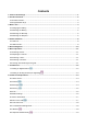
Contents 1. Items in the Package ..........................................................................................................................1 2. Product Overview ...............................................................................................................................2 2.1 Product Controls .............................................................................................................................2 2.2 Programmable Keys ....................................
. Troubleshooting ...............................................................................................................................20 10. Care and Cleaning ..........................................................................................................................22 11. Optional Accessories .....................................................................................................................
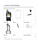
1. Items in the Package Please unpack carefully and check that all items listed below are received. If any item is missing or damaged, please contact your dealer. Radio Unit Battery Power Adapter Belt Clip Strap Documentation Kit Warning .1. Please keep distance of 25mm from the body, when speaking.
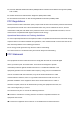
2. Product Overview 2.1 Product Controls 3 12 22 13 23 4 1 20 5 2 14 21 6 7 8 9 10 11 No. Part Name 15 16 17 18 19 No.
No. Part Name No. Part Name 7 ○ Up Key 19 ○ Down Key 8 ○ Volume -/Left Key 20 ○ Charging/Data Connector 9 ○ Call Key 21 ○ Earpiece Connector 10 ○ P1 22 ○ Battery Cover Open-up 11 ○ P2 23 ○ Battery Cover 12 ○ Strap Hole 2.2 Programmable Keys For enhanced convenience, you may request your dealer to program the SK1, P1, P2 and P3 as shortcuts to certain feature.
3. Before Use 3.1 Charging the Battery Caution: Make sure the radio is powered off before charging. Read the Safety Information Booklet in advance to get necessary safety information. To achieve optimal battery performance, please charge the battery for at least 5 hours before initial use. Please use the power adapter specified by the Company to charge the radio (with battery attached). Charging Diagram is listed below.
Note: Upon being charged after the radio is powered off due to low battery voltage, the radio displays a black screen. 3.2 Attaching the Battery To attach the battery, perform the following steps. Note: Turn off the radio before removing the battery.
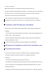
3.3 Attaching the Belt Clip To attach the belt clip, perform the following steps. 3.4 Attaching the Earpiece Step 1 Open the connector cover as ① shown. Step 2 Align the index of the earpiece with that of the radio and connect the earpiece to the radio as ② shown. Step 3 Turn the earpiece clockwise as ③ shown to fasten it.
7
4. Status Indication 4.1 LCD Icon Icon Name Icon Radio Status Battery Power Icon More bars indicate more battery power. Low power for the current channel. TX Power Icon High power for the current channel. Accessory Icon An accessory is connected. Direct Mode Operation: Under this mode, radios can communicate with each other directly. Operation Mode Icon Repeater Mode Operation: Under this mode, radios communicate with each other via a repeater. Monitor Icon The Monitor feature is enabled.
Icon Name Icon Radio Status Indicates Group Contact in the contact list. Indicates All Call during a call. Indicates All Call Contact in the contact list. 4.2 LED Indicator LED Indication The Radio Status LED indicator flashes Powering on. green. The indicator LED glows Receiving. green. The indicator LED glows Transmitting. red. The LED indicator flashes Scanning. orange slowly. The LED indicator flashes Emergency. orange rapidly.
5. Menu Navigation The following menu list shows all the menus of the radio. You can customize the menu item in the radio via your dealer. To select and confirm the options shown in the menu, press the OK/Menu key and then press the Up or Down key to select your needed option, finally press the OK/Menu key. This manual only describes the path to the menus, for example, to access the contact list, go to “Contact -> Contact List”.
6. Basic Operation 6.1 Powering On/Off Long press the Power On/Off/ESC key to power on and off the radio. 6.2 Adjusting the Volume After the radio is powered on, you can press the Volume +/Right key to increase the volume and press the Volume -/Left key to decrease it. 6.3 Selecting a Zone You can include a group of channels with the same property into a zone for convenient management. The radio supports 16 zones, each of which consists of up to 16 channels.
7. Call Services After the radio is powered on, you can make and receive calls. To ensure optimal volume of the receiving radio, keep the microphone about 2.5 to 5 centimeters away from your mouth when transmitting. Private call: It is a voice call between individual user and another individual user. Group call: It is a voice call between one individual user and a predefined group of users. All parties in the group can communicate with each other.
5. Radio A can receive the call without any operation. When receiving, the LED indicator glows green and the radio displays the icon . Radio A can hold down the PTT key to talk when the LED indicator glows orange and the radio displays the icon . Contact List or Call Log 1. Radio A and Radio B select the same digital channel. 2. Radio A accesses the contact list via menu “Contact -> Contact List”, “Contact -> Favorite Contact” or “Call Log -> Outgoing/Incoming/Missed”. 3.
8. Features and Operations 8.1 Home Screen The feature allows the radio to return to the home screen directly. To return to the home screen directly, press . 8.2 Contact You can manage the contacts via the “Contact” menu. 8.2.1 Contact List The Contact List is used to save the Call Alias, Call Type and Call ID of Private Call/Group Call/All Call contacts which is preset by the dealer. You can access the “Contact List” menu via the ‘Contact’ menu or by pressing or the programmed Contact List key.
The outbox can save up to 10 sent messages. When the Outbox is full, the earliest message will be overwritten by the latest one automatically. 8.4 Call Log The radio keeps track of all recent outgoing, incoming and missed private calls only. It can store up to 10 call logs. When the Call Log is full, the earliest call log will be overwritten by the latest one automatically. Operation: To access this menu, press the OK/Menu key and select the “Call Log” menu; or press the programmed Call Log key directly.
To stop scanning, go to “Menu -> Scan -> Scan On/Off” and select “Off”, or press the programmed Scan key again. Note: The radio cannot scan analog channel and digital channel at the same time. 8.6 Radio Settings You can optimize performance of your radio via the following configuration according to your actual needs and preferences. Operation: Go to “Settings -> Radio Settings” to configure the corresponding features. 8.6.
Off: the backlight will remain off. On: the backlight will remain on. Timed: If no operation or signal transmission/receipt occurs within the time preset by the dealer, the backlight will be turned off automatically. 8.6.5 LED Indicator You can set whether to activate the LED indicator. You can set the LED indication for specific features such as TX, RX, Scan, Low Battery, and the like. 8.6.6 Tone You can turn the tone on and off. If it is set to Silent, the radio will give no tones at all. 8.6.
Service Operation the digital channel. hold down the PTT key. To send messages. Press the programmed One Touch Call key. 8.9 Time-Out-Timer The feature is to prevent you from occupying a channel for an extended period. If the TX time (60s preset by dealer) expires, the radio will automatically terminate transmission and keep beeping. To stop beeping, please release the PTT key.
Hold down the programmed Monitor Momentary key to enable the feature, then the radio displays the icon ; release this key to disable the feature. 8.12 Squelch Off Momentary With the Squelch Off Momentary feature enabled, your radio’s speaker will keep unmuted no matter whether carrier is present. Operation: Hold down the programmed Squelch Off Momentary key to enable this feature, then the radio displays the icon and sounds background noise. To disable the feature, release this key.
9. Troubleshooting Phenomena Analysis Solution The battery may be improperly Remove the battery and then attach it. installed. The battery power may be Recharge or replace the battery. used up. Power-on Failure. Clean the battery contacts. If the problem The battery may be poorly cannot be solved, contact your dealer or connected due to dirtied or authorized service center for inspection and damaged battery contacts. repair. The battery voltage may be Recharge or replace the battery. low.
Phenomena Analysis Solution signaling. interference at the same frequency. And change the signaling settings for all portable radios at the same time. You may be too far away from Move towards other members. other members. You may locate unfavorable in position. an For example, your communication Move to an open and flat area, and restart the may radio to try again. The noise is too be blocked by high loud. buildings or frustrated in the underground areas.
10. Care and Cleaning To guarantee optimal performance as well as a long service life of the product, please follow the tips below. Product Care Do not pierce or scrape the product. Keep the product far away from substances that can corrode the circuit. Do not hold the product by its earpiece cable directly. Attach the accessory connector cover when the accessory is not in use. Product Cleaning Caution: Turn off the product and remove the battery before cleaning.
11. Optional Accessories The following item is the main optional accessories for the radio. For more information of other accessories, please consult your local dealer. Caution: Use the accessories specified by the Company only. If not, The Company shall not be liable for any loss or damage arising out of use of unauthorized accessories.