IMPORTANT! IMPORTANTE! DO NOT DESTROY NO DESTRUIR Manual Installation de Instalación and y Maintenance Mantenimiento Manual with Safety Information con Información sobre Seguridad and Parts List y Lista de Partes RECOMMENDED SPARE PARTS HIGHLIGHTED IN GRAY LAS PARTES DE REPUESTO RECOMENDADAS SE RESALTAN EN GRIS Model ProSort 100 Effective August, 2000 Bulletin # 471 HYTROL CONVEYOR CO., INC. © COPYRIGHT 2000–HYTROL CONVEYOR CO., INC.
● Table of Contents 2 ● Tabla de Contenido Warning Signs . . . . . . . . . . . . . . . . . . . .3 Señales de Advertencia . . . . . . . . . . . . .3 INTRODUCTION Receiving and Uncrating . . . . . . . . . . . .4 INTRODUCCION Recepción y Desembalaje . . . . . . . . . . .4 INSTALLATION Installation Safety Precautions . . . . . . . .5 Location . . . . . . . . . . . . . . . . . . . . . . . .6 Conveyor Set-Up . . . . . . . . . . . . . . . . . .7 Electrical Equipment . . . . . . . . . . . . . .
● Warning Signs In an effort to reduce the possibility of injury to personnel working around HYTROL conveying equipment, warning signs are placed at various points on the equipment to alert them of potential dangers. Please check equipment and note all warning signs. Make certain your personnel are alerted to and obey these warnings. Shown below are typical signs that are attached to this equipment.
INTRODUCTION INTRODUCCION This manual provides guidelines and procedures for installing, operating, and maintaining your conveyor. A complete parts list is provided with recommended spare parts highlighted in gray. Important safety information is also provided throughout the manual. For safety to personnel and for proper operation of your conveyor, it is recommended that you read and follow the instructions provided in this manual.
INSTALLATION INSTALACION ● Installation Safety ● Medidas de Seguridad Precautions for Conveyors and Related Equipment al Instalar Transportadores y Equipos Relacionados GUARDS AND GUARDING Interfacing of Equipment. When two or more pieces of equipment are interfaced, special attention shall be given to the interfaced area to insure the presence of adequate guarding and safety devices. Guarding Exceptions.
● Location ● Localización 1. . . Refiérase a la estructura del edificio para evitar que cualquier maquinaria, columna o pared obstruya la ubicación del transportador. Revise que el plano sea el correspondiente. 2. . . Determine el flujo del producto. La figura 6A indica el flujo con relación al motor. 3. . . Use las etiquetas de secuencia ubicadas en el extremo de cada sección de transportador para que sean colocadas en la posición correcta, cerca al área de instalación (Figura 6A). 1. . .
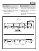
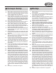
● Conveyor Set-Up 1. . . Mark a chalk line on floor to locate center of the conveyor. 2. . . Attach supports and vibration pads to all conveyor sections shown in Figures 6B and 8A. Adjust elevation to required height. Hand tighten bolts only at this time. 3. . . During installation, check to make sure each bed section is square. Measure the diagonals from corner to corner of the frame. If they are not equal the frame must be squared.
FIGURE 8A FIGURE 8B CHAIN GUIDES MUST BE EVEN AT JOINT BED SPACER (ESPACIADOR DE CAMA) (LAS GUIAS DE CADENA DEBEN SER UNIFORMES EN LA UNION) WEARSTRIP CHAIN GUIDE (GUIA DE CADENA) BED SPACER (ESPACIADOR DE CAMA) SIDE CHANNEL SPLICE (CANAL LATERAL) (EMPALME) SIDE CHANNEL (CANAL LATERAL) VIBRATION PAD (PROTECTORES DE VIBRACION) PIVOT PLATE (PLACA PIVOTE) CONVEYOR CHANNEL SECTION JOINT (CANAL DEL TRANSPORTADOR) (SECCION DE UNION) FIGURE 8C FIGURE 8D END SWITCH FIGURE 8E INTERMEDIATE SWITCH
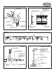
FIGURE 9A MOUNTING BRACKET (FASTEN TO CONVEYOR CHANNEL) FIGURE 9B (PLACA DE MONTAJE [SUJETAR AL CANAL DEL TRANSPORTADOR]) MAIN AIR SUPPLY LINE OIL CUP (SUMINISTRO PRINCIPAL DE AIRE) (RECIPIENTE DE ACEITE) AIR SUPPLY TO AIR VALVUES (SUMINISTRO DE AIRE A LAS VALVULAS) ADJUSTMENT SCREWS (TORNILLOS DE AJUSTE) 1/2" NPFT INLET (ENTRADA DE 1/2" NPFT) GAUGE (MEDIDOR) OIL LINES TO BRUSHES (LINEAS DE ACEITE PARA LAS BROCHAS) 1/2" UNION TEE (UNION TE DE 1/2") FILTER/REGULATOR (REGULADOR/FILTRO) BOWL GUA
● Electrical Equipment ● Equipo Eléctrico WARNING! Electrical controls shall be installed and wired by a qualified electrician. Wiring information for the motor and controls are furnished by the equipment manufacturer. ADVERTENCIA! Los controles eléctricos deben ser conectados e instalados por un electricista calificado. La información sobre el cableado del motor y los controles será proporcionada por el fabricante del equipo.
All such emergency stop devices shall be easily identifiable in the immediate vicinity of such locations unless guarded by location, position, or guards. Where the design, function, and operation of such conveyor clearly is not hazardous to personnel, an emergency stop device is not required. The emergency stop device shall act directly on the control of the conveyor concerned and shall not depend on the stopping of any other equipment.
OPERATION OPERACION ● Operation Safety Precautions ● Medidas de Seguridad A) Only trained employees shall be permitted to operate conveyors. Training shall include instruction in operation under normal conditions and emergency situations. B) Where employee safety is dependent upon stopping and/or starting devices, they shall be kept free of obstructions to permit ready access. C) The area around loading and unloading points shall be kept clear of obstructions which could endanger personnel.
MAINTENANCE ● Maintenance Safety Precautions MANTENIMIENTO ● Medidas de Seguridad en el Mantenimiento A) Maintenance, such as lubrication and adjustments, shall be performed only by qualified and trained personnel. A) El mantenimiento, tal como lubricación y ajustes, debe ser realizado solamente por personal calificado y entrenado.
● Controlling the ProSort A good software package is essential for proper operation of the ProSort sorter. With proper controls, the sorter will provide accurate, efficient, reliable sorting for many years. Inadequate controls, however, may result in poor sorter performance and are the leading cause of “crashes” and other mechanical failures of the sorter itself. Every sortation system is different, which means that the controls for the system are custom and unique to that system.
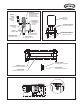
in the switch, the guide pin of the shoe may collide with the point of the lower switch block, resulting in damage to the switch and potentially costly downtime. The ProSort has two control components at each divert switch that work together to accurately time the divert switch movement or operation, eliminating the need for the controls provider to do so. These components are the smart prox and the high-speed solenoid air valve.
HIGH-SPEED SOLENOID AIR VALVE The solenoid air valve is used to receive the smart prox output signal and provide air to the proper end of the divert switch cylinder to move and hold the switch in either the “home” or “divert” positions. The valve used is specially designed for the high speed operation necessary for proper divert switch timing. The two inputs of the solenoid are non-polarized, allowing either lead to be used as input or ground for the valve. The solenoid requires 24VDC, 4W to operate.
inductive proximity switches as the electrical interface to the system controls. There are two types of safety switches in the sorter: 1. . . Shoe positions safety switches are switch mechanisms inside the sorter that trip if a divert shoe passes them that is not in its proper track. They are also used to detect foreign objects that might fall between the slats and enter the interior of the sorter. They are made to detect problems on both the upper and return portions of the sorter.
pulse output. Refer to the encoder manufacturer’s installation manual. provided with the sorter, for wiring instructions. CHAIN OILER SOLENOID The chain oiler is used to provide automatic lubrication of the carrying chains during sorter operation. When the oiler solenoid valve is energized, oil is allowed to gravity feed from the oiler reservoir, through metering valves, to brushes located above the return chains in the sorter.
3. . . Check for the proper gap between packages for safe sorting. It is important to check for the proper gap here, even if it has been set prior to this point, to insure that the packages are truly spaced properly. Attempting to sort packages with too little gap between them can cause jams. Note: The minimum gap necessary for sorting a package is a function of the width of the package. The following charts should be used in checking for proper gap. 2. . .
Some Control Do’s and Dont’s Recomendaciones del Control The following are recommendations to assist in the design and installation of system controls that are interfacing with ProSort sorters. Lo siguiente son las recomendaciones para auxiliar en el diseño e instalación de los sistemas de controles correspondientes al ProSort. • Do not place 24VDC control wires in the same wireway with AC power wires, especially if the AC power exceeds 240 volts.
FIGURE 21A LOWER SWITCH BLOCK (INTERRUPTOR INFERIOR DE BLOQUEO) UPPER SWITCH BLOCK (INTERRUPTOR SUPERIOR DE BLOQUEO) ROD END (EXTREMO DEL EJE) DIVERT SWITCH (NON DIVERT POSITION) (INTERRUPTOR DESVIADOR [POSICION DESVIADORA]) FIGURE 21B LOWER SWITCH BLOCK (INTERRUPTOR INFERIOR DE BLOQUEO) UPPER SWITCH BLOCK (INTERRUPTOR SUPERIOR DE BLOQUEO) DIVERT SWITCH (DIVERT POSITION) (INTERRUPTOR DESVIADOR [POSICION]) ROD END (EXTREMO DEL EJE) CYLINDER ROD (ACTUADOR) JAM NUT (CONTRA TUERCA) FIGURE 21C 1/32"
● Carrying Chain Installation The carrying chains are shipped on marked spools, cut to proper length for each ProSort conveyor. Steps for installing are as follows: 1. . . Disconnect electrical power to drive motor to prevent accidental start up. 2. . . Remove the plug from the motor fan guard, exposing the hex on the motor shaft. Use this shaft to rotate the motor manually. 3. . . Check alignment of chain guides by using two short pieces of chain with slats assembled to pins.
FIGURE 23A ALLOW FROM 5" TO 6" AT INSTALLATION (PERMITA DE 5 A 6 PULGADAS DE ESPACIO DURANTE LA INSTALACION) FIGURE 23B FIGURE 23C CARRYING CHAIN (CADENA) OW FL CONECTOR LINK (ENLACE) FIGURE 23D 23
● Locating the Spurs The take-away spurs must be mounted properly on the divert sections of the ProSort to insure proper diverting of product. The following installation guidelines apply to both powered and gravity spurs. 1. . . Attach spurs to the sorter by bolting the spur attachment bracket to the spur mounting nuts in the unistrut channel on the sorter side channel (Figure 24A). Support the spurs as required. Hand-tighten bolts only at this time. 2. . .
● Divert Switch Removal Procedure The ProSort is designed for easy removal of the divert switch assembly for maintenance or replacement. In order to remove the switch assembly follow the following steps. 1. . . Remove the cover located on the side of the sorter channel at the divert switch (Figure 25A). 2. . . Unplug the elbow from the fitting on the solenoid air valve by pushing in on the red flange of the fitting and then pulling on the elbow. 3. . . Disconnect proximity switch connector. 4. . .
● Trouble Shooting The following charts list possible problems that may occur in the operation of the ProSort. TROUBLE SHOOTING DRIVES TROUBLE CAUSE 1) Jam eye blocked. 2) Tripped internal safety switch. Conveyor will not start or shuts off automatically during operation. Conveyor takes long time to reach speed or conveyor jerks when starting. 3) Pop-up rollers “UP”. 4) Proximity switch for internal safety switch or pop-up rollers mis-adjusted or defective. 5) Low air pressure. a) Regulator set low.
● Resolviendo Problemas La siguiente gráfica muestra una lista de posibles problemas que pueden ocurrir durante la operación del ProSort RESOLVIENDO PROBLEMAS DE TRANSMISION PROBLEMA El transportador no arranca o se detiene automáticamente durante la operación. El transportador se demora en alcanzar la velocidad deseada o da tirones al arrancar. Los bloques “brincan” cuando desvian. CAUSA SOLUCION 1) Despeje la obstrucción del sensor.
● Preventive Maintenance Checklist The following is a general maintenance checklist which covers the major components of your conveyor. This will be helpful in establishing a standard maintenance schedule.
● Lista de Mantenimiento Preventivo La siguiente es una lista de verificación del mantenimiento preventivo, la cual cubre los principales componentes de su transportador. Esta será útil para establecer un programa estándar de mantenimiento. HORARIO COMPONENTE MOTOR REDUCTOR CADENAS CATARINAS DE LAS CADENAS TUBOS ACCION SUGERIDA Revisar la Lubricación Revisar la Tensión (Ver Pag.
● Preventive Maintenance Details Carrying Chains—Check lubrication. Chains will appear moist properly lubricated. Slats—Check physical condition. Check slats for cleanliness and straightness. Slats may be cleaned by wiping with degreaser type solvent such as a denatured alcohol. Replace any bent slats. Divert Switches—Check physical condition. Switches must be kept in good physical condition and free and clear of all foreign matter. Check operation.
● How to Order Replacement parts ● Como Ordenar Partes de Repuesto Included in this manual are parts drawings with complete replacement parts lists. Minor fasteners, such as nuts and bolts, are not included. Dibujos de las partes con listas completas de las refacciones están incluidos en este manual. Aseguradores menores, como tornillos y tuercas no están incluídos. When ordering replacement parts: 1. . . Contact Dealer from whom conveyor was purchased or nearest HYTROL Distributor. 2. . .
● Model ProSort 131 Parts Drawing Dibujo de Partes del Modelo ProSort 131 109 118 72 110 79 105 94 86 111 93 81 91 89 83 88 87 98 85 114 107 108 32 108 106 103 104 112 113 73 90 92 96
● Model ProSort 131 Parts Drawing Dibujo de Partes del Modelo ProSort 131 66 60 97 100 82 80 62 101 63 64 117 46 123 69 63 116 58 68 65 55 39 119 38 67 99 75 78 77 95 84 74 76 102 59 57 56 61 119 70 53 54 33
● Model ProSort 131 Parts Drawing Dibujo de Partes del Modelo ProSort 131 35 48 49 120 121 71 124 126 34 122 125 127 45 51 52
● Model ProSort 131 Parts Drawing Dibujo de Partes del Modelo ProSort 131 50 34 32 41 28 29 33 30 18 5 23 25 17 24 7 26 12 3 15 8 27 40 2 1 4 10 47 37 3 36 115 21 22 11 21 13 14 16 22 31 49 42 9 6 35
● Model ProSort 131 Parts List Lista de Partes del Modelo ProSort 131 See Page 31 for Information on How To Order Replacement Parts Vea la Página 31 para información sobre como ordenar partes de repuesto Recommended Spare Parts Highlighted in Gray Las Partes de Repuesto Recomendadas se Resaltan en Gris Ref. No. 1 2 3 4 5 6 7 — — 8 — — 9 — — 10 11 12 — — 13 14 15 16 17 18 19 20 21 22 23 24 25 26 27 28 29 30 31 32 33 34 — — 35 36 37 38 39 36 Part No.
● Model ProSort 131 Parts List Lista de Partes del Modelo ProSort 131 Ref. No. 78 79 80 81 82 83 — — — — 84 — — — — 85 86 87 88 89 90 91 — — — — 92 93 94 95 96 97 98 99 100 101 102 103 — — — — — — — — — — — — — — — — — — — — Part No.
● Divert Switch Assembly Parts Drawing Dibujo del Ensamble Interruptor Desviador 27 1 30 21 18 26 17 22 25 19 15 16 20 9 5 24 4 32 6 14 7 8 12 23 3 11 28 29 34 31 13 33 36 35 38 10 2
● Divert Switch Assembly Parts List Lista de Partes del Interruptor Desviador See Page 31 for Information on How To Order Replacement Parts Vea la Página 31 para información sobre como ordenar partes de repuesto Recommended Spare Parts Highlighted in Gray Las Partes de Repuesto Recomendadas se Resaltan en Gris Ref. No. 1 — — 2 — — 3 — — 4 5 6 7 8 9 10 11 12 13 14 15 16 Part No. — B-17048 B-17047 — B-17050 B-17049 — B-23596 B-23595 B-23597 B-23592 019.2215 032.21121 032.2113 040.1005 041.198 041.798 041.
● Safety Switch Assembly Parts Drawing Dibujo del Ensamble de Interruptor de Seguridad 4 3 9 10 5 6 7 8 2 40 1
● Safety Switch Assembly Parts List Lista de Partes del Interruptor de Seguridad See Page 31 for Information on How To Order Replacement Parts Vea la Página 31 para información sobre como ordenar partes de repuesto Recommended Spare Parts Highlighted in Gray Las Partes de Repuesto Recomendadas se Resaltan en Gris Ref. No. 1 2 — — — — — — — Part No. B-23792 — 069.715 069.7151 069.7152 069.7153 069.7154 069.7155 069.7156 Description Switch Sensor Plate (Specify OAW) Switch Sensor Belt 26 in. OAW 30 in.
● Notes 42
www.hytrol.com HYTROL CONVEYOR COMPANY, INC.