
Installation Guide
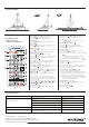

2. Installation
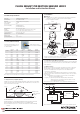
1. Technical Specifications
Product type Daylight harvest PIR motion sensor
Operating voltage 220~240VAC 50/60Hz
Rated load 1600W (resistive); 800VA (capacitive)
Power consumption < 0.5W
Detection angle 360
o
Detection area (Max.)*
Detection range 10% / 50% / 70% / 100%
Hold time 2s / 30s / 1min / 5min / 10min / 15min / 20min / 30min
Stand-by time 0s / 10s / 1min / 5min / 10min / 30min / 1h / +
Stand-by dimming level 10% / 20% / 30% / 50%
Daylight threshold 50 ~ 500Lux, Disable
Warming up time 30s
Operating temperature -20
o
C ~ +50
o
C
3. Rotary Switch Settings
Detection
range
0
1
2
3
4
5
6
7
8
9
A
B
C
D
E
F
100%
100%
100%
100%
100%
100%
100%
100%
100%
100%
100%
100%
100%
100%
100%
100%
5s
1min
5min
5min
5min
5min
10min
10min
10min
10min
20min
20min
30min
30min
30min
5s
10s
5min
10min
+∞
+∞
+∞
30min
+∞
+∞
+∞
1h
+∞
+∞
+∞
+∞
10s
10%
10%
10%
10%
10%
30%
10%
10%
10%
30%
10%
30%
10%
30%
50%
10%
Disable
50Lux
50Lux
75Lux
100Lux
200Lux
50Lux
75Lux
100Lux
200Lux
100Lux
200Lux
100Lux
200Lux
400Lux
100Lux
Hold
time
Stand-by
time
Stand-by
dimming level
Daylight
threshold
A rotary switch is built inside the sensor for
scene selection / fast programming. Total
16 channels available :
Note: settings can also be changed by remote control HRC-11. The last action controls.
8
4. Functions
The built-in daylight sensor can read ambient natural light and switch off the fixture automatically
whenever artificial light is unneeded (natural light lux level exceeds daylight threshold).
Note: if the stand-by time is preset at "+∞", the fixture never switches off even when natural light
is sufficient.
The motion sensor is employed, but only activated on the manual press of the push switch, light
keeps on in the presence, dims down in the absence, and eventually switches off automatically
in the long absence.
4.1 Daylight Harvest (Daylight Regulating)
4.2 Lux Off Function
4.3 Semi-auto Function (Absence Detection)
FLUSH MOUNT PIR MOTION SENSOR HIR22
Installation and Instruction Manual
Rotary switch preset (Please
see the location in 2. Installation)
Warnings:
1. Installation of the sensor involves connecting it to the mains supply. This work must be
carried out by a specialist in accordance with electrotechnical regulations.
2. Disconnect supply before installing.
Channel
With the help of push-switch, this sensor maybe over-ridden by the end-users to switch on/off
the lights manually, or adjust the light brightness during motion hold-time. This makes the
product more user-friendly and offers more options to fit for extra-ordinary demands.
* Short push (<1s): on/off function;
ON → OFF: the light turns off immediately and cannot be lighten for a certain time (equals to
hold time preset) even there is movement is detected. After this period, the sensor goes back to
auto sensor mode.
OFF → ON: the light turns on 100% and goes to auto sensor mode, even when ambient
Lux level exceeds the daylight threshold.
* Long push (>1s): adjust the target lux level by turning the light up or down. Both the
adjustment on remote control and push switch can overwrite each other,
the last adjustment remains in memory.
Note: end-user can choose either function 4.3 or 4.4 for application. Default function is 4.4.
4.4 Manual Override
Daylight sensor measures the available surrounding natural light, calculates how much electrical light is
needed to reach the total lux expected. The demand is given to the LED driver by 1-10V signal, so as to
deliver the needed amount of electric light.
0 24
Light level
Time (hrs)
Normal Electric Light
Daylight controlled light
Energy Saving Zone
Natural light
Hold time
Stand-by time
Infrared receiver
Photocell
LED indicator
PIR
Rotary switch preset
1
3
4
2
(1) Sensor inset
(2) Lens pluggable
(3) Protection cover (covers the
high-voltage terminals, and leaves
the 1-10V terminals exposed).
(4) Ceiling (drill hole O 70mm).
70mm
64.7
o85
68.1
73.3
56
HIR22-20181226-A1
Blind
A
B
Blind
Note1: the blinds are optional, they may be inserted
behind the lens for focussing the detection range.
5. Wiring Diagram
Note: if neither function 4.3 nor 4.4 is desired, simply leave the “push” terminal disconnected.
LED Driver
1-10V
+
-
L
N
P
L
N
1-10V
+
-
L’ N N L
Note2:We recommend the mounting distance between sensor to sensor
should be more than 2m to prevent sensors from false-triggering.
Installation Height : 5m
Detection Range (Ø) :10m