FUEL SYSTEM Return To Main Table of Contents [MPI SYSTEM] GENERAL . . . . . . . . . . . . . . . . . . . . . . . . . . . . . . . . . . . . . . . . . . . . . . MPI SYSTEM . . . . . . . . . . . . . . . . . . . . . . . . . . . . . . . . . . . . . . . . . 2 14 INJECTOR AND THROTTLE BODY . . . . . . . . . . . . . . . . . . . . 5 4 THROTTLE BODY . . . . . . . . . . . . . . . . . . . . . . . . . . . . . . . . . . . . . 57 FUEL TANK . . . . . . . . . . . . . . . . . . . . . . . . . . . . . . . . . . . . . . . .
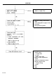
GENERAL SPECIFICATIONS Fuel tank Capacity Fuel filter 45 lit. (11.9 U.S. gal., 9.9 lmp.gal.) Type Fuel pump High pressure type Type Driven by Throttle body Throttle position sensor (TPS) Electrical, in-tank type Electric motor Type Resistance Output voltage at curb idle Idle speed control (ISC) servo motor Variable resistor type 3 . 5 - 6 . 5 KD 0.48-0.
GENERAL No. 1 cylinder TDC sensor Type Crankshaft angle sensor Photo diode sensor Type Output actuator Injector Photo diode sensor Type Number Coil resistance Purge control solenoid valve Electromagnetic type 4 13-16 R at 20°C (68°F) Type EGR control solenoid valve [California Only] ON/OFF type Type Fuel pressure regulator Regulated pressure Duty cycle type solenoid valve 330 kPa (3.
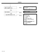
SERVICE STANDARD BTDC 5° ± 2° at curb idle 700 ± 100 rpm 0.48-0.
GENERAL SPECIAL TOOLS 31-5
TROUBLESHOOTING When checking and correcting engine troubles, it is important to start with an inspection of the basic systems. If one of the following conditions exists, (A) engine start failure, (B) unstable idling or (C) poor acceleration, begin ‘by checking the following basic systems. 1. Power supply 1) Battery 2) Fusible link 3) Fuse 2. Body ground 3. Fuel supply 1) Fuel line 2) Fuel filter 3) Fuel pump 4. Ignition system 1) Spark plugs 2) High-tension cables 3) Distributor 4) Ignition coil 5.
GENERAL MPI TROUBLESHOOTING PROCEDURES PROBLEM Engine will not start o Battery 1. Connection 2. Specific gravity, charging system 3. Drive belt 4.
GENERAL o Ignition timing-adjust [Refer to page 27-5] o Fuel line (leakage, deformation) o Fuse o Fuel pump [Refer to page 31-24] o Fuel filter o Fuel pressure regulator o Wiring connections o Power to ECU 1. Fusible links 2. Fuses 3. MPI control relay o Engine coolant temperature sensor o Intake air temperature sensor o Injection signal circuit 1. Injector wiring 2.
GENERAL PROBLEM Rough idle or engine stalls Trouble Codes o Using voltmeter [Refer to page 31--32] o Using MUT [Refer to page 31-35] o Oil filler cap o Oil dipstic o Vacuum hose connections o PCV hose o EGR system o o o o o Fuel line (leakage, deformation) Fuses Fuel pump [Refer to page 31-24] Fuel filter Fuel pressure regulator Element-Clean or replace Idle speed-Adjust [Refer to page 31-20] Ignition timing-Adjust [Refer to page 27-5] 31-9
GENERAL o Fuel pump [Refer to page 20-24] o Fuel filter o Fuel regulator Injection condition o Wiring connections o Power to ECU 1. Fusible links 2. Fuses 3. MPI control relay o Engine coolant temperature sensor o Intake air temperature sensor o Injection signal circuit 1. Injector wiring 2.
GENERAL PROBLEM Engine hesitates or accelerates poorly o Clutch-slip o Brake-drag o Oil filler cap o Oil dipstic o Hose connections o PCV hose o EGR system Element-Clean or replace Trouble codes o Using voltmeter [Refer to page 31-32] o Using MUT [Refer to page 31-35] o High tension cables o Distributor o Ignition coil, ignition Ignition timing-Adjust [Refer to page 27-5] o Fuel pump [Refer to page 31-24] o Fuel filter o Fuel pressure regulator 31-11
31-12
GENERAL Fuel Tank And Fuel Line Symptom Probable cause Remedy Engine malfunctions due to insufficient fuel Bent or kinked fuel pipe or hose Clogged fuel pipe or hose Clogged fuel filter of in-tank fuel filter Water in fuel filter Repair or replace Clean or replace Replace Replace the fuel filter or clean the fuel tank and fuel lines Clean or replace Replace supply Dirty or rusted fuel tank interior Malfunctioning fuel pump (Clogged filter in the pump) Evaporative emission control system malfunctions
MPI SYSTEM MPI SYSTEM GENERAL INFORMATION The basic function of the MPI (Multi-Point Injection) system is to control the air-fuel ratio, based on data from various sensors. The MPI system is composed of three basic systems: Fuel, Intake and Electronic Control. Fuel System Fuel is supplied under constant pressure to the injectors by an electric fuel pump in the fuel tank. The pressure is controlled by the pressure regulator.
MPI SYSTEM LOCATION OF COMPONENTS A. Air conditioner relay B. Air flow sensor C. ISC servo (Motor position sensor) D. Throttle position sensor E. Coolant temperature sensor F. Power transistor G. Crankshaft angle sensor H. injector I. Oxygen sensor J. Inhibitor switch K. MPI control relay L. Diagnosis terminal M. Vehicle speed sensor N. Electronic control unit O. EGR temperature sensor (California vehicles only) P. Power steering oil pressure switch Q. Purge control solenoid valve R.
MPI SYSTEM 31-16
MPI SYSTEM
MPI SYSTEM 31-18
MPI SYSTEM SERVICE ADJUSTMENT PROCEDURES Idle Speed Check Procedure CAUTION The improper setting (throttle valve opening) will increase exhaust gas temperature at deceleration, reducing catalyst life greatly and deteriorating exhaust gas cleaning performance. It also has effect on fuel consumption and engine braking. Checking conditions: o Engine coolant temperature is 80 o Lights, electric cooling fan and all o Transaxle is in neutral [“P” or “N” o Steering wheel is a straight ahead power steering).
Idle Speed Control (ISC) And Throttle Position Sensor (TPS) Adjustment Adjustment conditions: o Engine coolant temperature is 80 to 95°C (176 to 205°F) o Lights, electric cooling fan and all accessories are off. o Transaxle is in neutral [“P” or “N” range for A/T vehicles]. o Steering wheel is a straight ahead position (Vehicles with power steering). 1. Loosen the accelerator cable. 2. 3. Connect the multi-use tester to the diagnostic connector in the fuse box.
MPI SYSTEM 4. Turn the ignition switch to ON (do not start the engine) and leave it in that position for 15 seconds or longer; then check to be sure that the idle speed control servo is fully retracted to the curb idle position. NOTE When the ignition switch is turned to ON, the ISC plunger extends to the fast idle position opening; then, after 15 seconds, it retracts to the fully close (curb idle) position. Motor position sensor : 0.9V 5. Turn the ignition switch OFF. 6.
MPI SYSTEM 13. Turn the ignition switch to ON (do not start engine) and check that the TPS output voltage is as specified. If the multi-use tester is used, press code No. 14 and read the voltage. Standard value . . . . . . . . . . . . . . . . . . . . . . . . . . . . . 0.48-0.52V 14. Connect a digital-type voltmeter between terminal 24 and terminal 19 of the ECU, if the multi-use tester is not used. NOTE 1. Do not disconnect the ECU connector from the ECU. 2. Use an accurate digital voltmeter. 15.
MPI SYSTEM Throttle Body (Throttle Valve Area) Cleaning NOTE Disconnect the air intake hose from the throttle body, and check the throttle valve surface for carbon deposits, rotating the valve. Apply the spray cleaning solvent on the valve to remove carbon deposits. 1. Run the engine until warm. 2. Remove the air intake hose from the throttle body. 3. Spray cleaning solvent into the valve through the throttle body intake port and leave it for about 5 minutes. 4.
MPI SYSTEM Overfill Limiter (Two-way Valve) Replacement 1. Disconnect the vapor hoses and the overfill limiter. Fuel Sender Replacement 1. Remove the fuel filler cap to lower the fuel tank’s internal pressure. 2. Disconnect the harness connector from the fuel sender. 3. Remove the fuel sender unit installation screws, then remove the fuel sender assembly from the fuel tank. Fuel Pump Operation Check 1. Turn the ignition switch to OFF. 2.
MPI SYSTEM Fuel Pressure Test 1. Reduce the internal pressure of the fuel pipes and hoses by the following procedures. 1) Disconnect the fuel pump harness connector at the rear of the fuel tank. 2) Start the engine and after it stalls, turn the ignition switch to OFF. 3) Disconnect the battery negative (-) terminal. 4) Connect the fuel pump harness connector. 2. Remove the upper, eye bolt while holding the fuel filter nut securely.
MPI SYSTEM 7. Measure the fuel pressure when the vacuum hose is connected to the pressure regulator. Standard value . . . . . . . . . . . . . . . . . . . . . . . Approx. 270 kPa (2.75 kg/cm2, 39 psi) 8. If the results of the measurements made in steps (6) and (7) are not within the standard value, use the table below to determine the probable cause, and make the necessary repairs. Condition Probable cause Remedy Fuel pressure too low a. Clogged fuel filter. b.
MPI SYSTEM 10. Reduce the fuel pressure in the fuel line. 11. Disconnect the high pressure hose and remove the fuel pressure gauge from the delivery pipe. CAUTION Cover the hose connection with a shop towel to prevent splashing of fuel caused by residual pressure in the fuel line. 12. Install a new O-ring in the groove at the end of the high-pressure hose. 13. Connect the high pressure fuel hose to the delivery pipe, and tighten the screws to the specified torque. 14. Check for fuel leaks.
MPI SYSTEM Purge Port Vacuum Check Checking Condition Engine coolant temperature: 80-95°C (176-205°F) 1. Disconnect the vacuum hose from the throttle body purge hose fitting and connect a vacuum pump. 2. Start the engine and check to see that, after increasing the engine speed, vacuum remains fairly constant. NOTE If there is no vacuum created, it is possible that the throttle body port may be restricted and require cleaning.
MPI SYSTEM MPI SYSTEM INSPECTION If the MPI system components (sensors, ECU, injector, etc.) fail, interruption or failure to supply the proper amount of fuel for engine operating conditions will result. Therefore, the following situations will be encountered. 1. Engine is hard to start or does not start at all. 2. Unstable idle. 3. Poor driveability.
MPI SYSTEM o o o o o o o o Motor position sensor Engine coolant temperature sensor Crank angle sensor No.1 cylinder top dead center sensor Barometric pressure sensor Injector Fuel pump EGR temperature sensor (California Vehicles Only) SELF-DIAGNOSIS The electronic control unit monitors the input/output signals at all times. When the ECU detects a problem for a specified time, the electronic control unit memorizes the trouble code, and outputs a signal to the self-diagnositc output terminal.
CHECKING PROCEDURE (SELF-DIAGNOSIS) CAUTION 1) If the battery voltage is low, no trouble codes will be stored. Be sure to check the battery voltage before starting the test. 2) Diagnostic codes will be erased if the battery or the ECU harness is disconnected. Do not disconnect the battery before the diagnostic codes are read. 3) After checks and repairs are completed, disconnect the (-) ground cable for 15 seconds or more to make sure that the codes are erased.
MPI SYSTEM Inspection Procedure (Using Voltmeter) 1. Connect the voltmeter to the self diagnosis connector. 2. Turn on the ignition switch, and indication of electronic control unit memory contents will immediately start. If the system is in normal operating condition, the pointer of voltmeter indicates a normal pattern. If any abnormality is in the memory, the pointer of voltmeter will deflect, indicating an abnormal item as described in “Diagnosis chart”.
MPI SYSTEM output preference order Diagnosis item Trouble code Output signal pattern Check item (Remedy) N O.
MPI SYSTEM output preference order Diagnosis item Trouble code Check item (Remedy) Output signal pattern No. Memory 11 Barometric pressure sensor 25 Retained o Harness and connector (If harness and connector are normal, replace the barometric pressure sensor assembly.
MPI SYSTEM CHECKING (USING THE MULTI-USE TESTER) 1. Turn the ignition switch OFF. 2. Connect the harness connector of the multi-use tester to the diagnostic connector in the fuse box. 3. Connect the power-source terminal of the multi-use tester to the cigarette lighter socket. 4. Turn the ignition switch ON. 5. Use the multi-use- tester to make the system and sensor checks.
MPI SYSTEM Check points Check conditions Test specification Normal o Check in accordance with the diagnostic code. (Note that the diagnostic code will be erased if there is disconnection or damage to the electronic control unit back-up power-supply circuit.) o If various diagnostic codes are output, the most frequent cause is damage or disconnection of the power-supply or ground circuit. The pulsations of the fuel flow can be felt.
MPI SYSTEM Check points Injectors o Service data o Item No.41 Check conditions o Engine cranking Test specification Probable cause of malfunction Listen for operation Injectors should be heard o Injector malfunction. o Improper contact of the connector and control relay contacts. Engine coolant temperature Injector activation time (msec.) o Malfunction of the engine coolant temperature sensor. o Malfunction of the ignition switch-ST. [°C (°F)] 0 (32) Approx. 17 20 (68) Approx.
MPI SYSTEM Sensor Check Check points Check conditions Self-diagnostic output o Engine: idling (2 minutes or more after engine start) Oxygen sensor o Service data o Item No.11 o Engine warm (Make the mixture lean by engine speed reduction, and rich by racing.
MPI SYSTEM Check points Intake-air temperature sensor o Service data o Item No.13 Throttle-position sensor o Service data o Item No.14 Motor position sensor o Service data o Item No.1 5 Check conditions Test specification o Ignition switch: Air temperature Temperature °C (°F) ON, or engine °C (°F) running -20 (-4) -20 (-4) 0 (32) 0 (32) 20 (68) 20 (68) 40 (104) 40 (104) 80 (176) 80 (176) o Ignition switch: ON Warm by using Increases a hair dryer or other method.
MPI SYSTEM Check points Motor position sensor o Sensor data o Item No.15 Check conditions The compressor clutch must be activated when the air conditioner switch is switched ON.
MPI SYSTEM Check conditions Check points Barometric pressure sensor o Service data o Item No.25 o Ignition switch: ON Altitude m (ft.) Test specification Pressure mm Hg 0 (0) 760 600 (1,968) 710 1,200 (3,937) 660 1,800 (5,905) 610 o Engine: 2,000 rpm Gradually close Decreases. the air-intake duct by hand. Idle switch o Service data o Item No.
MPI SYSTEM Check points EGR temperature o Engine: warm sensor [California vehicle only) o Service data o Item No.43 Injectors o Actuator test o Item No.1-4 Injector o Service data o Item No.41 Test specification Check conditions Engine condition Temperature °C (°F) 700 rpm (Idle) 70 (158) or less 3,500 rpm 70 (158) o Disconnect or more the vacuum hose (yellow) stripe from the A port nipple of the throttle body, and pinch the hose end with your fingers.
MPI SYSTEM Check points Air conditioner relay o Service data o Item No.49 Check conditions o Engine: idle after warm-up Test specification Air conditioner switch Air conditioner relay OFF OFF (compressor clutch nonactivation) ON ON (compressor clutch activation) Probable cause of malfunction o If the air conditioner relay output is abnormal, check the air conditioner signal input circuit and the air conditioner system.
MPI SYSTEM MPI SYSTEM COMPONENTS INSPECTION Air Flow Sensor (AFS) 1. Connect a voltmeter between 6 and 3 of AFS connector. Terminal 6 : Sensor ground Terminal 3 : AFS output 2. Warm the engine and bring it to a normal idle. 3. Measure the voltage between terminals. Engine speed (rpm) Idling Output voltage (V) 2.7-3.2 3,000 NOTE If the air flow sensor fails, the intake air volume cannot be measured and as a result, normal fuel injection control is no longer available.
MPI SYSTEM Reference 150 350 760 Pressure mmHg (kPa, psi) (20, 2.9) (49, 6.9) (103, 15) Central voltage (V) 0.79 1.84 4.00 4. Replace the air flow sensor if necessary. intake Air Temperature Sensor 1. Disconnect the air flow sensor connectors. 2. Measure the resistance between the terminals 4 and 6. Terminal 4 : intake air temperature output Terminal 6 : Sensor ground 3. Temperature ºC (ºF) Resistance (KD) 0 (32) 5.4-6.6 20 (68) 2.33-2.97 80 (176) 0.31-0.
MPI SYSTEM 3. Temperature ºC (ºF) Resistance (KD) 0 (32) 5.9 20 (68) 2.5 40 (104) 1.1 80 (176) 0.3 If the resistance deviates from the standard value greatly, replace the sensor. Throttle Position Sensor (TPS) 1. Disconnect the throttle position sensor connector. 2. Measure the resistance between terminals 1 and 4 of the throttle position sensor connector. Terminal 1 : Sensor ground Terminal 4 : Sensor power Standard value . . . . . . . . . . . . . . . . . . . . . . . . . . . . . 3.5-6.
MPI SYSTEM 3. Connect an analog type ohmmeter between terminals 1 and 3. Terminal 1 : Sensor ground Terminal 3 : Sensor output 4. Slowly open the throttle valve from the idle position to the fully open position and check that the resistance values change smoothly with the opening of the throttle valve. Standard value . . . . . . . . . . . . . . . Approx 0.5 - (3.5-6.5) kfl 5. If the resistance is out of specification, or if the change is not smooth, replace the throttle position sensor.
Motor Position Sensor (MPS) 1. Connect an ohmmeter between terminals 4 and 1 of the motor position sensor connector. Terminal 1 : Sensor power Terminal 4 : Sensor ground 2. Measure the resistance of the terminals. Standard value . . . . . . . . . . . . . . . . . . . . . . . . . . . . 4-6 kfi 3. Attach an ohmmeter between terminals 2 and 4 of the motor position sensor connector. Terminal 2 : MPS output Terminal 4 : Sensor ground 4.
MPI SYSTEM 5. If the standard value is not achieved, or if the change is not smooth, replace the ISC servo assembly. No.1 Cylinder TDC Sensor And Crankshaft Angle Sensor 1. Connect a voltmeter between terminals 1 and 2, and 1 and 3. Terminal 1 : Sensor ground Terminal 2 : Crank angle signal Terminal 3 : No.1 TDC signal 2. 3. Measure the output voltage of the terminals while cranking the engine. Sensor Terminal Voltage No.1 cylinder TDC sensor Ground 0.2-1.
MPI SYSTEM Engine Oxygen sensor output voltage Remarks Increase RPM Min. 0.6V Richens air/fuel mixture Tightening torque Oxygen sensor . . . . . . . . . . . . . . . . . . . . . . . . . . . . . . . . . . . . . . . 39-49 Nm (400-500 kg.cm, 29-36 lb.ft) Vehicle Speed Sensor The vehicle speed sensor uses a reed type switch. The speed sensor built in the speedometer converts the speedometer gear revolution (vehicle speed) into pulse signals, which are sent to the ECU.
MPI SYSTEM Resistance Measurement Between Terminals 1. Disconnect the connector for the injector. 2. Measure the resistance between the terminals. Standard value . . . . . . . . . . . . . . . . 13-16 Cl [at 20°C (68ºF)] 3. Connect the connector for the injector. Idle Speed control (ISC) Servo 1. Measure resistance between terminal 1 and 2 using an ohmmeter. Standard value : 5-35 Sz [at 20°C (68ºF)] 2.
MPI SYSTEM Control Relay CAUTION When applying battery voltage directly, make sure that it is applied to the correct terminal. Otherwise, the relay could be damaged. NOTE Failure of the control relay interrupts power supply to the fuel pump, injectors and ECU, resulting in start failure. 1. Check continuity between the terminals when the relay coil is energized and when it is not. NOTE In the following tables, the arrows indicate the direction of the current flow.
MPI SYSTEM Power Transistor The power transistor is installed on the intake manifold; it functions to control the ignition timing by controlling the ignition coil primary current by signals from the ECU. 1. Disconnect the power transistor connector. 2. Connect a power supply of 1.5V (one dry cell) between the power transistor and then check for continuity between terminals 3 and 2 under power-ON and power-OFF conditions.
INJECTOR AND THROTTLE BODY (MPI) INJECTOR AND THROTTLE BODY COMPONENTS TORQUE : Nm (kg.cm, lb.ft) REMOVAL 1. Release residual pressure from the fuel line to prevent fuel from spilling. CAUTION Cover the hose connection with a shop towel to prevent fuel from leaking out due to residual pressure in the fuel line.
INJECTOR AND THROTTLE BODY (MPI) 2. Remove the delivery pipe with the fuel injector and pressure regulator. CAUTION 1. Be careful not to drop any injectors when removing the delivery pipe. 2. Be aware that fuel may flow out when removing the injector. INSPECTION 1. Measure the resistance of the injectors between the terminals using an ohmmeter. Resistance . . . . . . . . . . . . . . . . . . . . .13-16n [at 20°C (68ºF)] 2. If the resistance is not within specifications, replace the injector.
INJECTOR AND THROTTLE BODY (MPI) 5. When installing the delivery pipe, check to be sure that the insulator is correctly inserted into the delivery pipe’s installation hole. 6. When connecting the fuel pressure regulator to the delivery pipe, apply light oil or fuel to the O-ring, and then insert, being careful not to damage the O-ring. 7. When connecting the high pressure fuel hose to the delivery pipe, apply fuel to the hose union, and then insert, being careful not to damage the O-ring.
THROTTLE BODY (MPI) THROTTLE BODY COMPONENTS TORQUE : Nm (kg.cm, lb.ft) REMOVAL CAUTION The throttle valve must not be removed.
THROTTLE BODY (MPI) 1. Remove the throttle position sensor by unscrewing the Phillips-head screws. NOTE Except when necessary for replacement, the throttle position sensor must not be removed. 2. Remove the ISC servo assembly. NOTE 1) Except when necessary for replacement, the ISC servo assembly should not be removed. 2) The ISC servo assembly should not be disassembled. 3. Use an open-end wrench or box wrench to remove the adjustment screw. INSPECTION Cleaning Throttle Body components 1.
FUEL TANK COMPONENTS REMOVAL 1. To reduce the internal pressure of the fuel lines and hoses, first start the engine and then disconnect the electrical fuel pump connector. NOTE Be sure to reduce the fuel pressure before disconnecting the fuel line and hose otherwise fuel will spill out.
FUEL TANK (MPI) 2. Disconnect the battery cable from the negative terminal of the battery. 3. Remove the fuel tank cap. 4. Remove the drain plug and drain the fuel. 5. Disconnect the return hose and vapor hose. 6. Disconnect the fuel gauge unit connector.
FUEL TANK (MPI) 7. Disconnect the high pressure hose from the fuel tank. 8. Detach the fuel filler hose and leveling hose. 9. Loosen the two self-locking nuts, that hold the tank in position and remove the two tank bands. 10. Remove the fuel vapor hose and the fuel tank. INSPECTION 1. 2. 3. 4. 5. Check Check Check Check Check the hoses and the pipes for cracks or damage. the fuel tank cap for proper operation. the fuel tank for deformation, corrosion or cracking.
FUEL TANK (MPI) 6. Test the two-way valve for proper operation. 7. To check the two-way valve, lightly breathe into the inlet and outlet. If air passes through after slight resistance, then the valve is good. INSTALLATION 1. Confirm that the pad is fully bonded to the fuel tank, and install the fuel tank by tightening the self-locking nuts to the tank bands until the rear end of the tank band contacts the body. 2. Connect the leveling hose to the tank and approximately 40 mm (1.6 in.) at the filler neck.
FUEL TANK (MPI) 5. To connect the high pressure hose to the fuel pump, temporarily tighten the flare nut by hand; then tighten it to the specified torque. Be careful that the fuel hose does not twist. Tightening torque High pressure hose flare nut . . . . . . . . . . . . . . . . . . . . . . . . . 31-41 Nm (320420 kg.mm, 23-30 lb.ft) CAUTION When tightening the flare nut, be careful not to bend or twist the line to prevent damage to the fuel pump connection. 6.
FUEL LINE AND VAPOR LINE (MPI) FUEL LINE AND VAPOR LINE TORQUE : Nm (kg.cm, lb.ft) REMOVAL 1. Remove the upper eye bolt while holding the fuel filter nut securely and remove the high pressure fuel hose. CAUTION 1) Be sure to reduce the fuel pressure before disconnecting the fuel line and hose, otherwise fuel will spill out. 2) Cover the hose connection with a shop towel to prevent splashing of fuel that could be caused by residual pressure in the fuel line. 2.
FUEL LINE AND VAPOR LINE (MPI) INSPECTION 1. Check the hoses and pipes for cracking bending, deformation or restrictions. 2. Check the canister for restrictions. 3. Check the fuel filter for restrictions and damage. If a problem is found, repair or replace parts as necessary. INSTALLATION 1. Install the fuel vapor hose and return hoses. o If the fuel line has a stepped section, connect the fuel hose to the line securely, as shown in the illustration.
ENGINE CONTROL (MPI) ENGINE CONTROL TORQUE : Nm (kg.cm, Ib.ft) REMOVAL 1. Remove the bushing and inner cable of the accelerator arm side. 2. After disconnecting the accelerator switch connector, loosen the bolts of the accelerator arm bracket and remove.
ENGINE CONTROL (MPI) INSPECTION 1. 2. 3. 4. 5. 6. Check Check Check Check Check Check the the the the the the inner and outer cable for damage. cable for smooth movement. accelerator arm for deformation. return spring for deterioration. connection of the bushing to end metal fitting. accelerator switch for proper operation. INSTALLATION 1. When installing the return spring and accelerator arm, apply multi-purpose grease around each moving point of the accelerator arm. 2.
GENERAL (FBC) GENERAL INFORMATION (FBC SYSTEM) The Feedback Carburetor (FBC) system provides a positive air-fuel ratio control for maximum reduction of emissions. The Electric Control Unit (ECU) receives signals from various sensors and then modulates two solenoid valves (FBSV, SCSV) installed on the carburetor to control the air-fuel ratio. The ECU also controls the ignition timing, electric choke, throttle opener by switching on-off the solenoid valves.
GENERAL SPECIFICATIONS Fuel tank Capacity Fuel filter Type [In-line filter] Type [In-tank filter] Fuel pump 45 lit. (11.9 U.S.gal., 9.9 Imp.gal.) Cartridge type Open type Type Driven by Feed pressure Carburetor Mechanical diaphragm type Camshaft 19-25 kPa (2.76-3.63 psi) at 2,500 rpm Type Identification mark M/T A/T Throttle bore Primary Secondary Feedback solenoid valve (FBSV) Down-draft, 2-barrel, feed back type 472 (For Canada), 474 (For Federal) 475 (For Federal) 30 mm (1.181 in.) 32 mm (1.260 in.
GENERAL (FBC) Main jet Primary Secondary Main air jet Primary - First Second Secondary Pilot jet Primary Secondary Pilot air jet Primary - First Second Secondary Main nozzle Primary Secondary Throttle valve plate Thickness Primary Secondary Fuel closing angle Primary Secondary Full opening angle Enrichment jet Slow air jet Accelerating pump Diaphragm dia. Pump jet dia.
GENERAL (FBC) Oxygen sensor Type Vacuum switch Type Operating condition - ON OFF Vehicle speed sensor Top gear sensing switch Output actuator Cold mixture heater Zirconia sensor Contact type switch More than 40 kPa (5.8 psi) Less than 26 kPa (3.
GENERAL (FBC) SERVICE STANDARD BTDC 700 ± 800 ± 900 ± Basic ignition timing Curb idle speed Throttle opener adjusting rpm for electrical load Throttle opener adjusting rpm for air conditioner load TIGHTENING TORQUE Accelerator arm bracket to body Accelerator cable guide to body Carburetor attaching bolt Engine coolant temperature sensor Oxygen sensor Fuel tank drain plug 5º 50 50 25 ± 1º rpm rpm rpm Nm kg.cm lb.ft 8-12 3-5 15-20 20-40 39-49 78-98 80-120 30-50 150-200 200-400 400-500 800-1,000 5.
GENERAL (FBC) SPECIAL TOOLS 31-74
GENERAL (FBC) TROUBLESHOOTING When checking and correcting engine troubles, it is important to start with inspection of the basic systems. If you experience one of the followings, (A) engine start failure, (B) unstable idling or (C) poor acceleration, you should first check the following basic systems. 1. Power supply 1) Battery 2) Fusible link 3) Fuse 2. Body ground 3. Fuel supply 1) Fuel line 2) Fuel filter 3) Fuel pump 4.
GENERAL (FBC) Fuel Tank and Fuel Line Symptom Probable cause Remedy Engine malfunctions due to insufficient fuel supply Bent or kinked fuel pipe or hose Repair or replace Clogged fuel pipe or hose Clean or replace Clogged fuel filter or in-tank fuel filter Replace Water in fuel filter Replace the fuel filter or clean the fuel tank and fuel line Dirty or rusted fuel tank interior Clean or replace Malfunctioning fuel pump (Clogged filter in the pump) Replace Misrouted vapor lines Correct Dis
GENERAL (FBC) Carburetor and FBC System Engine will not start or start to hard Carburetor FBC system Rough idle or engine stalls Remedy Probable cause Symptom Carburetor FBC system Choke valve remains open-cold engine Clean choke bore and linkage Improper choke breaker operation Check and adjust choke breaker Electric choke malfunction Check electric choke body and choke valve operation Needle valve sticking or clogged Repair or replace Engine coolant temperature sensor malfunction Check
GENERAL (FBC) Engine hesitates or poor acceleration Remedy Probable cause Symptom Carburetor FBC system Acceleration pump malfunction Clean pump discharge.
GENERAL (FBC) Probable cause Symptom Poor fuel mileage FBC system Remedy Engine coolant temperature sensor malfunction Check by using checker (Check component and replace if faulty) Oxygen sensor malfunction Check by using checker (Check component and replace if faulty) Timing control system malfunction Check system.
GENERAL (FBC) FBC System Component 1. Electric Control Unit (ECU) Based on the information- from various sensors, the ECU determines (computes) ideal setting for varying operating conditions and drives the output actuators to control the air-fuel ratio. The ECU consists of an 8-bit microprocessor, random access memory (RAM), read only memory (ROM) and input/output (l/O) interface.
GENERAL (FBC) 2. Engine Coolant Temperature Sensor The engine coolant temperature sensor is installed in the engine coolant passage of the intake manifold. This coolant sensor is a thermistor. The ECU determines engine temperature by the sensor output voltage and utilize it to provide optimum fuel enrichment when the engine is cold. 3. Throttle Position Sensor (TPS) The TPS is a rotary type variable resistor that rotates together with the carburetor throttle shaft to sense the throttle valve angle.
GENERAL (FBC) 5. Oxygen Sensor 1) The oxygen sensor installed on the exhaust manifold makes use of the principles of solid electrolyte oxygen concentration cell. The‘ oxygen concentration cell is characterized by sharp change of the output voltage in the vicinity of the stoichiometric air-fuel ratio. 2) Using such characteristics, the oxygen sensor senses the oxygen concentration in the exhaust gas and feeds it to the ECU.
GENERAL (FBC) 7. Feedback Solenoid Valve (FBSV) The FBSV is installed in the carburetor float chamber cover. The ECU controls the air-fuel ratio by controlling the duty cycle of the FBSV. The higher is the duty ratio, the leaner becomes the air-fuel ratio. NOTE The duty cycle control means control of the solenoid valve energization rate by changing the ON time ratio T2/T 1 (called duty ratio) of 10 Hz pulse. 8. Slow Cut Solenoid Valve (SCSV) The SCSV is located in the carburetor float chamber cover.
GENERAL (FBC) FBC System Operation 1. The air-fuel ratio control is maintained by the ECU in one of two operating modes. 1) Closed loop control (Feedback control) After engine warm-up, the air-fuel ratio control is made by the feedback control based on the oxygen sensor signal. The oxygen sensor output voltage changes sharply at the stoichiometric ratio.
GENERAL (FBC) Distributor Advance Control System (Ignition Timing Control System) The distributor vacuum advance is a dual diaphragm type having main vacuum chamber and sub-vacuum chamber. To control the ignition timing, the ECU energizes the solenoid valves in the respective vacuum circuits of main vacuum chamber and subvacuum chamber. 1. Main Vacuum Timing Control 1) When the engine speed is near the idle speed (1,200 rpm or less), the ECU energizes the distributor advance control solenoid valve.
GENERAL (FBC) 2) When the engine speed increases to 1,200 rpm the ECU turns off the distributor advance control solenoid valve. Intake manifold vacuum is routed to the main vacuum chamber increasing ignition advance. When the engine starts to warm up [engine coolant temperatures: below 80°C (176°F), the solenoids are energized, allowing D port vacuum to reach main vacuum chamber. 2. Sub-vacuum Timing Control o Control at low altitude [approx. 1,200 m (3,900 ft.
GENERAL (FBC) Throttle Opener System (For power steering, electrical load) If the power steering oil pressure switch is turned on by high pump pressure the throttle opener control solenoid valve is energized to introduce intake manifold vacuum to the throttle opener. The throttle valve opens slightly, preventing engine speed drop caused by power steering load. When the engine speed drops below the set speed (1,200 rpm), the ECU keeps the power transistor on.
GENERAL (FBC) Throttle Opener Switch (For A/C) When the engine speed is below the set speed (1,200 rpm), the ECU keeps the power transistor on. When the air conditioner relay is turned on the throttle opener control solenoid valve is energized to introduce intake manifold vacuum to the throttle opener. The throttle valve opens slightly preventing engine speed drop caused by air conditioner load.
GENERAL (FBC) Cold Mixture Heater (CMH) Relay Control System The cold mixture heater is a Positive Temperature Coefficient (PTC) heater installed between the carburetor and intake manifold. When the engine coolant temperature is below 60°C (140°F), the ECU energizes the cold mixture heater relay. The closed relay supplies voltage to the cold mixture heater. The cool air-fuel mixture is heated and atomized by the heater before it reaches the combustion chamber for improved combustion.
GENERAL (FBC) Electric Auto Choke System In the carburetor electric choke system, a bimetal choke spring is heated by an electric heater (PTC heater*). As the bimetal spring is heated by the heater after start-up, the bimetal opens the choke valve gradually by thermal expansion and pushes down the stopper lever. The lower the temperature when the engine is started, the tighter the bimetal closes the choke valve, thus improving at cold weather starting.
GENERAL (FBC) 1. Choke Valve and Fast Idle Cam Operation 1) Before starting the engine, the throttle valve is in normal idle opening state. 2) Before starting the engine, depress the accelerator pedal to the floor, and the fast idle cam will turn clockwise. Release the accelerator pedal, and the lever will ride on the fast idle cam and the throttle valve will open.
GENERAL (FBC) 2. Operation of Choke Opener If the engine has been started with the throttle valve lever on the highest fast idle cam step then the engine speed will increase with the engine coolant temperature. This results in the engine overrun. In order to prevent such overrun, the choke opener is provided. 1) When the thermo valve closes as the engine coolant temperature rises [65°C (149°F)], the intake manifold vacuum acts on the fast idle breaker.
SERVICE ADJUSTMENT PROCEDURES (FBC) SERVICE ADJUSTMENT PROCEDURES FBC SYSTEM Inspection If FBC system components (sensors, carburetor control unit-computer, solenoid, etc.) fail, one of the following situations may be encountered. 1. Engine is hard to start or does not start at all. 2. Unstable idle. 3. Poor driveability. If any of above conditions is noted, first perform basic engine checks (ignition system malfunctions, incorrect engine adjustment, etc.).
SERVICE ADJUSTMENT PROCEDURES (FBC) 10. Turn the ignition switch to OFF. 11. Disconnect connectors of FBC checker and FBC harness connector from carburetor control unit and body side harness connectors. 12. Connect body side harness connector to carburetor control unit.
SERVICE ADJUSTMENT PROCEDURES (FBC) 31-95
SERVICE ADJUSTMENT PROCEDURES (FBC) SERVICE ADJUSTMENT PROCEDURES IDLE SPEED CHECK AND ADJUSTMENT Checking Conditions: o Engine coolant temperature is 80 to 95°C (176 to 205°F). o Engine lubricant temperature is over 80°C (176°F). o Lights, electric cooling fan and all accessories are off. o Transaxle is in neutral. 1. Set timing light and tachometer. 2. Start the engine and let it idle. 3. Check the basic ignition timing and adjust if necessary. Ignition timing . . . . . . . . . . . . . . . . . . . . . .
SERVICE ADJUSTMENT PROCEDURES (FBC) THROTTLE OPENER ADJUSTMENT For Operation Under Electrical Load The procedure that follows is to check and adjust the idle speed control operation of the throttle opener when electric load is applied. 1. 2. 3. 4. Make sure curb idle speed is within the specified speed. If outside the specified limits, readjust the speed to the nominal specification.
SERVICE ADJUSTMENT PROCEDURES (FBC) THROTTLE POSITION SENSOR (TPS) ADJUSTMENT 1. Loosen the accelerator cable enough. 2. Loosen the speed adjusting screw No. 1 (SAS 1) and No. 2 (SAS 2) sufficiently to close the throttle valve completely. Record the number of turns loosened. NOTE Turning the screw counterclockwise closes the valve. At this time, the fast idle control should have been released (the lever not resting on the fast idle cam). 3.
SERVICE ADJUSTMENT PROCEDURES (FBC) DASH POT CHECK AND ADJUSTMENT Checking Conditions: o Engine coolant temperature : 80 to 95°C (176 to 205°F). o Lights, electric cooling fan and accessories : Set to OFF o Transaxle : Neutral. 1. Start the engine and run at idle. 2. Open the throttle valve for full stroke of the rod until the free lever contacts SASS. 3. Close the throttle valve until SAS2 contacts the free lever and check the engine speed at that moment. 4.
SERVICE ADJUSTMENT PROCEDURES (FBC) ELECTRIC CHOKE SYSTEM CHECK AND INSPECTION CAUTION All carburetors have a tamper-proof choke. The choke-related parts are factory adjusted. The choke adjustment is not required during service, except when major carburetor overhaul or choke calibration related parts adjustments are needed by state or local inspections. 1. Check that the alignment marks on the electric choke and bimetal assembly are lined up. If not, align the marks.
SERVICE ADJUSTMENT PROCEDURES (FBC) INSPECTION OF CHOKE BREAKER SYSTEM o Check conditions of the choke valve according to procedures given in the table below.
SERVICE ADJUSTMENT PROCEDURES (FBC) 1. 2. After inspection of the choke breaker system, disconnect the vacuum hose from the choke breaker and make the following check. With the engine idling, close the choke valve lightly with a finger until the choke valve stops. Then, measure the choke valve to choke bore clearance. Standard value : 1.4-1.6 mm (0.055-0.063 in.) 3. If the clearance is not as specified, stop the engine, remove the bimetal assembly and adjust the rod end opening for standard clearance.
SERVICE ADJUSTMENT PROCEDURES (FBC) Fast Idle And Adjustment Inspection Conditions o Engine coolant temperature : 80 to 95°C (176 to 205°F). o Lights, electric cooling fan and accessories : Set to OFF. o Transaxle : Neutral o Air cleaner : Removed o Tachometer installed 1. Disconnect the vacuum hose (white stripe) from the choke opener.
SERVICE ADJUSTMENT PROCEDURES (FBC) 2. Set the lever on the second highest step of fast idle cam. 3. Start the engine and check the fast idle speed. Standard value: Vehicles with a manual transaxle Vehicles with an automatic transaxle 4. 2,800 rpm 2,700 rpm If the fast idle speed is out of specification, adjust with the fast idle adjusting screw. Information Adjusting direction Valve Fast idle speed Clockwise Large Increases Counterclockwise Small Decreases 5.
SERVICE ADJUSTMENT PROCEDURES (FBC) INSPECTION AND ADJUSTMENT OF ACCELERATOR CABLE FREE PLAY 1. Run the engine until it reaches the specified idle speed. 2. Confirm that the accelerator inner cable has no slack. 3. If it shows slack, adjust it as follows: 1) 2) Loosen the adjusting nut so that the throttle lever is free. Turn the accelerator adjusting nut to the point where the throttle lever just starts moving, then back off one turn and secure the lock nut. FUEL GAUGE UNIT REPLACEMENT 1. 2. 3. 4.
FUEL TANK (FBC) FUEL TANK COMPONENTS REMOVAL CAUTION When removing parts such as a fuel tank, rear suspension, etc., use a garage jack at the front of vehicle (Refer to GENERAL GROUP), to prevent the vehicle from tilting. When working on fuel tank, be sure the ignition is switched off. Avoid any source of heat or sparks, such as lights, smoking, etc. Prior to working on the fuel tank or lines, remove the fuel filler cap to release any pressure in the tank.
FUEL TANK (FBC) 1. Remove the drain plug to drain the fuel tank. NOTE Do not disconnect the in-tank filter except when the filter is replaced. 2. Loosen the fuel hose (main and return) clamps and disconnect the fuel hoses. 3. Disconnect the filler hose and breather hose from the filler neck. 4. After removing the protector (if so equipped) and fuel tank mounting band, drop the fuel tank slightly and disconnect the fuel gauge unit harness. 5. Remove the fuel tank. 6. Remove the fuel gauge unit as necessary.
FUEL LINE (FBC) FUEL LINE COMPONENTS 31-108
FUEL LINE (FBC) REMOVAL AND INSTALLATION 1. Pipes should be secured firmly with clips and clamps to prevent looseness. 2. With the hoses and pipes are installed, make sure that they are not distorted or loose. 3. Route the hoses and tubes correctly and fit their ends securely. 4. Install clips and clamps in correct direction to make sure that they do not interfere with neighboring objects. INSPECTION 1. Check the hoses and pipes for cracks, bend, deformation, deterioration or clogging. 2.
FUEL PUMP (FBC) FUEL PUMP REMOVAL 1. Disconnect the battery ground cable. 2. Disconnect the fuel inlet, outlet and return hoses at fuel pump. Remove the two fuel pump mounting bolts, and remove the fuel pump and push rod. 4. Remove the fuel pump gaskets and insulator. 3. INSPECTION Checking Leakage If there is oil or fuel leaks from breather hole, oil seal or diaphragm in fuel pump is defective. Replace fuel pump assembly.
FUEL PUMP (FBC) Inlet Valve Test To test the inlet valve, connect a vacuum gauge on the inlet fitting while the line is disconnected. 1. Start engine or turn over with starting motor. 2. There should be a noticeable vacuum present. 3. If blow-back is present, inlet valve is not seating properly and a new pump should be installed. 4. If fuel pump does not perform to above test requirements, a new fuel pump should be installed. Pressure Test 1.
FUEL PUMP (FBC) FUEL PUMP TROUBLESHOOTING 31-112
CARBURETOR CARBURETOR CONSTRUCTION 31-113
CARBURETOR COMPONENTS 1. Throttle return spring 2. Damper spring 3. Throttle return spring bracket 4. Throttle opener/dash pot 5. Hose 6. Vacuum delay valve 7. Hose 8. Screw 9. Pin 10. Float 11. Needle valve 12. Needle valve seat 13. O-ring 14. Packing 15. Retainer 16. Feedback solenoid valve (FBSV) 17. O-ring 18. O-ring 19. Retainer 20. Slow cut solenoid valve (SCSV) 21. O-ring 22. O-ring 23. Plate 24. Bimetal assembly 25. Packing 26. Connector 27. Cover 28. Diaphragm 29. Spring seat 30. Spring 31.
CARBURETOR COMPONENTS 52. 53. 54. 55. 56. 57. 58. 59. 60. 61. 62. 63. 64. 65. 66. Bracket Float chamber cover gasket Steel ball Weight Ball Plug O-ring Ball Screw Gasket Main jet (primary) Main jet (secondary) Cover Spring Diaphragm 67. 68. 69. 70. 71. 72. 73. 74. 75. 76. 77. 78. 79. 80. 81. Enrichment jet valve Enrichment jet Spring Ball Pump cover assembly Diaphragm Spring Pump body Gasket Mixing body Vacuum hose Depression chamber Throttle position sensor (TPS) Lever Adjusting screw 82. 83. 84. 85.
CARBURETOR REMOVAL 1. 2. 3. 4. 5. 6. Disconnect battery ground cable. Remove air cleaner. Disconnect the throttle cable from carburetor. Disconnect the vacuum hoses from carburetor. Disconnect connectors for solenoid valves and TPS. Place a container under fuel fittings of carburetor to catch any fuel that may be trapped in fuel line and disconnect the fuel hoses from the carburetor inlet nipples. 7. Remove carburetor mounting bolts and carefully remove the carburetor from engine.
CARBURETOR 4. Pull the hose with delay valve off the nipple of choke breaker. 5. Remove the float chamber cover screws “B” to remove the throttle body. 6. Remove the screws “A” to remove the float chamber cover from main body. 7. To remove the float chamber cover assembly, insert a screw driver blade between the enrichment cover and the float chamber cover as illustrated and lightly pry and lift up slowly. CAUTION Do not apply excessive force. 8.
CARBURETOR 9. Using flat blade screwdrivers, pry up the needle valve seat at both edges to remove. CAUTION Use care not to damage the float chamber cover when pushing up the needle valve seat. 10. Remove the retainer of the feedback solenoid valve (FBSV). 11. Using a screwdriver or other tool with a thin flat end, push the stopper portion and remove the two terminals from behind the connector.
CARBURETOR 13. Remove the retainer and pull out the slow cut solenoid valve. 14. Using a screwdriver or other tool with a thin flat end, push the stopper section and remove the two terminals from behind the connector. 15. To remove the bimetal assembly, grind away the head of the two rivets of the bimetal assembly using a hand grinder or other tool and remove the screw. 16. Remove the plate and the bimetal assembly. 17.
CARBURETOR 18. Remove the three screws attaching the Bowl Vent Valve (BVV) cover to the float chamber. 19. Remove the plastic vent hosing, housing cover and the two springs. 20. Remove the bowl vent valve diaphragm shaft. CAUTION Carefully pull the diaphragm out of the float chamber cover so that rubber vent seal slides off the diaphragm shaft. NOTE Be careful not to misplace the two small springs positioned on either side of the plastic vent housing. 21.
CARBURETOR 22. Remove the three screws attaching the choke vacuum breaker cover, then remove the choke break cover, springs, diaphragm and linkage assembly. NOTE Of the two diaphragm springs, the outer one is longer. 23. Remove the choke bracket. 24. Unscrewing the four screws, remove the choke opener.
CARBURETOR 25. Remove the pilot jets and main air jet. NOTE When removing the jets, use a screwdriver that is an exact fit for their slot and work carefully to prevent damage. 26. Carefully lift and swing up the roll-over device weight from the bottom of the float chamber, then use a magnet to remove the roll-over steel ball. NOTE Remove the float chamber gasket and pour the remaining fuel contained in the float chamber into a container. 27. Remove the accelerator pump outlet check ball and weight.
CARBURETOR 29. Remove the main jets. NOTE When removing the main jets, use a screwdriver that is an exact fit and work carefully to prevent damage. 30. Remove the three screws attaching the enrichment valve cover to the enrichment housing on the float chamber. 31. Remove the cover, spring and diaphragm. 32. Unscrew the enrichment valve from the housing. 33. Using a screwdriver, loosen the enrichment jet and take out the spring and ball from the enrichment jet valve. CAUTION The valve has many small parts.
CARBURETOR NOTE When reinstalling, apply thread sealant to the screws and be sure the pump body, gasket and cover are properly positioned. 36. Remove the E-clip and outside washer on the secondary throttle shaft and slide the diaphragm spring link off the throttle shaft. 37. Remove the two screws attaching the diaphragm bracket to throttle body and remove the secondary throttle diaphragm. 38. Using a 10 mm wrench, remove the nut attaching the accelerator pump lever to the throttle shaft.
REASSEMBLY Perform reassembly in reverse of disassembly procedure, paying special attention to the following items: 1. Clean all parts before assembly. 2. Check to be sure that no clogging is in the air passages and fuel passages. 3. Check for smooth operation of throttle and choke linkage. If the operation is not smooth, clean them up. Then may be replaced at this time to ensure proper carburetor performance. 4.
CARBURETOR 2) Install the plate and temporarily tighten the screw. 3) Align the mating marks. 4) Set the rivet as illustrated. 5) While keeping the mating marks aligned, install the bimetal assembly with a hand riveter or similar tool. 6) Tighten the screw. 7) Install terminal to the connector at correct position.
CARBURETOR INSPECTION General Description Check the following and repair or replace parts if necessary. 1. Check the fuel paths (jets) and air paths (jets or orifices) for clogging. If clogged, wash thoroughly with cleaning solvent or detergent and blow by compressed air. Do not use metal wire or other metal pieces. 2. Check the diaphragms for damage and cracks. 3. Check that the needle valve operates lightly. If the valve is hard to slide or is binding, repair or replace.
CARBURETOR 4. Measure resistance between the terminals. SCSV coil resistance . . . . . . . . . . 48-60 fl [at 20°C (68°F)] Feedback Solenoid Valve (FBSV) 1. Apply battery voltage directly to the feedback solenoid valve terminals. 2. Check that the valve. operates with a click. 3. Check that the jet is free from clogging. 4. Using a circuit tester, check that there is not continuity between the solenoid valve body and terminals.
CARBURETOR 5. Measure resistance between the terminals. FBSV coil resistance . . . . . . . . . . . 54-66 0 [at 20°C (68°F)] Bimetal Assembly Using a circuit tester, measure resistance between the terminal and body. Bimetal resistance . . . . . . . . . . . . . Approx. 6 0 [at 20°C (68°F)l Dash Pot Check that the dash pot operates normally. Resistance must be felt when the dash pot is pulled. When the rod is released it must return quickly to the original position.
CARBURETOR Throttle Position Sensor (TPS) 1. Measure resistance between terminals 1 and 2 of the throttle position sensor. TPS resistance . . . . . . . . . . . . . . . . . . . . . . . . . . . . . 3.5-6.5 Kn 2. Check the body for crack and damage. Fast Idle Opening 1. Set the lever on the mark (scribed line) of fast idle cam. 2. Measure the primary valve to throttle bore clearance. Fast opening (drill diameter) M/T . . . . . . . . . . . . . . . . . . . . . . . . . . . . . . 0.93 mm (0.037 in.) A / T . . .
CARBURETOR Unloader Opening 1. 2. Lightly press the choke valve with a finger to fully close it. In this state, fully open the throttle valve and measure the choke valve to choke bore clearance. Standard value. . . . . . . . . 1.9-2.1 mm (0.075-0.083 in.) 3. If the clearance is out of specification, bend the throttle lever at illustrated portion to adjust the clearance to the standard value. Choke Breaker CAUTION Check and adjust with the bimetal assembly removed. 1.
CARBURETOR INSTALLATION 1. 2. 3. 4. 5. 6. 7. 8. 9. 10. Inspect the mating surfaces of carburetor and intake manifold. Be sure both surfaces are clean and free of nicks, burrs or other damage. Place a new carburetor gasket on intake manifold surface. Carefully place the carburetor on intake manifold. Install carburetor mounting bolts and tighten alternately, a little at time, to compress carburetor gasket evenly.
ENGINE CONTROL (FBC) ENGINE CONTROL TORQUE : Nm (kg.cm, lb.ft) REMOVAL Accelerator Cable 1. Loosen the accelerator cable adjusting nut. 2. Disconnect the accelerator cable from either the throttle lever. 3. Disconnect the accelerator cable from the accelerator arm.
ENGINE CONTROL (FBC) 4. Disconnect the accelerator cable guide from the fire wall, and then remove the accelerator cable. Accelerator Pedal 1. Loosen the accelerator cable adjusting nut, and disconnect the accelerator cable from the accelerator arm and remove the accelerator pedal. 2. Remove the return spring from the accelerator arm. 3. Remove the cotter pin from the accelerator arm shaft, and then remove the accelerator arm from the accelerator arm bracket. INSPECTION 1. 2. 3. 4. 5.
ENGINE CONTROL (FBC) 2. 3. 4. 5. To prevent entry of exhaust fumes, apply semi-drying type sealant to the bolt mounting hole, and then tighten the accelerator arm bracket. Make sure that the accelerator cable is laid without sharp bends. Inspect the play of accelerator cable. Install parts and torque to specification.