PRINTSPEC: EN2050/3010-2010v1 © 2010 MIDLAND INTERNATIONAL INC.
Thank you for purchasing a Hyundai Air Compressor. Please register your product in order for us to ensure your continuous satisfaction with our product. This manual covers the safety, operation, and maintenance procedures for the HPC-2050 and HPC-3010. All information in this publication is based on the latest product information available at the time of approval for printing. No part of this publication may be reproduced without written permission.
CONTENT 1. 1.1 1.2 1.3 1.4 1.5 1.6 1.7 1.8 1.9 1.10 1.11 1.12 2. 3. 4. 5. 6. 7. 8. 9. 10.
1.1 - GENERAL OPERATION SAFETY 1. Always perform a pre-operation check before using the air compressor. 2. Operators of the unit should always be wearing appropriate approved eye and hearing protection. Under some conditions, long durations of use may contribute to hearing loss. 3. Always operate the air compressor according to the instructions for safe and dependable service. 4. Always clean and properly maintain the equipment after use. 5. To avoid harm, never operate the compressor in an enclosed area.
withstand specific operating pressures. Never make adjustments or substitute parts to alter the factory set operating pressures. 1.5 - ATTACHMENTS AND ACCESSORIES SAFETY 1. Do not exceed the pressure rating of air tools, spray guns, air operated accessories, air tires, hoses, and other inflatables. Exceeding pressure ratings may cause them to explode or become damaged, resulting in serious injury. 2.
4. All electrical work must be performed by a qualified or licensed/certified electrician. 1.9 - RISK TO BREATHING 1. Always operate the compressor in a well-ventilated area. 2. Wear appropriate safety masks to reduce the risk of inhaling any harmful vapours. 3. Do not breathe compressed air from the compressor. The compressed air is not breathable and may contain carbon monoxide, toxic vapours, and/or solid particles. 4.
SECTION 2 - SPECIFICATIONS MODEL HPC-2050 HPC-3010 RUNNING HORSEPOWER 1/3 HP 1/3 HP MAX PSI 100 PSI 100 PSI SCFM @ 40 PSI 0.5 CFM 0.5 CFM SCFM @ 90 PSI 0.4 CFM 0.4 CFM 2 Gal 2.6 Gal TANK SIZE SECTION 3 FEATURES Pressure Switch This controls the power to the motor and the cut-in/cut-out pressure settings. Also serves as the Auto-On/Off positions for the unit. Safety Valve This valve allows excess tank pressure to escape into the atmosphere.
Allows for easy attachment and removal of the air hose. Motor Thermal Overload Protector If the motor begins to overheat, this protector will shut off the motor.
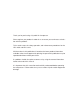
SECTION 5 - PARTS LIST (HPC 2050) 10 HPC 2050 / HPC 3010 User Manual
1 M5*50 Bolt 35 Elbow 2 Cylinder head 36 Rubber hose 3 Cylinder head support 37 Pressure switch 4 Rubber gasket 38 Tank 5 Valve plate 39 Drain valve 6 Gasket 40 Dual-adapter 7 End cap 41 Φ0.
24 Driving gear 58 Terminal ring cover 25 Motor 59 Terminal ring cover 26 M3*30 bolt 60 Wire nail 27 Spring washer 61 Self tapping screw 28 Fan 62 Self tapping screw 29 Motor cover 63 Cross recessed pan head screw 30 Φ6 jump ring 64 Tooth face washer 31 Φ8 rubber support 65 Ring terminal 32 M6 double-screw bolt 66 Power cord cover 33 M6 nut 67 Screw 34 6 flat washer HPC 2050 / HPC 3010 User Manual
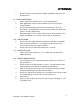
PARTS LIST (HPC 3010) HPC 2050 / HPC 3010 User Manual 13
1 M5*50 Bolt 35 Elbow 2 Cylinder head 36 Rubber hose 3 Cylinder head support 37 Pressure switch 4 Rubber gasket 38 Tank 5 Valve plate 39 Drain valve 6 Gasket 40 Dual-adapter 7 End cap 41 Φ0.
24 Driving gear 58 Terminal ring cover 25 Motor 59 Terminal ring cover 26 M3*30 bolt 60 Wire nail 27 Spring washer 61 Self tapping screw 28 Fan 62 Self tapping screw 29 Motor cover 63 Cross recessed pan head screw 30 Φ6 jump ring 64 Tooth face washer 31 Φ8 rubber support 65 Ring terminal 32 M6 double-screw bolt 66 Power cord cover 33 M6 nut 67 Screw 34 6 flat washer SECTION 6 - START-UP & OPERATION INITIAL INSPECTION All air compressors have been inspected carefully
INITIAL BREAK-IN PROCEDURE The following instructions should be followed before the first time the compressor is operated in order to optimize the life of the compressor and to help prevent any damage to the unit. 1. Make sure the regulator knob is turned fully counter-clockwise. 2. Plug the power cord into a properly grounded power outlet. 3. Open the drain valve in order to allow air to escape and prevent pressure from building up inside the tank. 4. Turn the ON/OFF switch to the ON position. 5.
SECTION 7 - MAINTENANCE Proper maintenance is important in order to ensure safe, economical, and trouble-free operation. Improper maintenance may cause the air compressor to malfunction and can lead to serious injuries or death. Shut off the compressor before performing any maintenance. When the engine is running, make sure the area is well ventilated. The compressed air may contain harmful vapours or particles. Use authorized parts or their equivalent.
NOTICE: 1. Service more frequently when used in dusty areas. 2. Should be serviced by an authorized service dealer. 3. Must be serviced by an authorized Hyundai Service Dealer. Failure to do so will void the warranty. SECTION 8 - TROUBLESHOOTING Many troubleshooting procedures present hazards which can result in severe personal injury or death. Only trained and experienced service personnel with knowledge of fuels, electricity, and machinery hazards should perform service procedures.
Moisture in discharged compressed air • Compressor does not or is slow to come up to speed • Compressor runs excessively hot • • • • • • Condensation in air tank caused by humidity Compressor located in damp or humid area • • Defective motor or pump Defective pressure switch Use of an extension cord • High duty cycles Compressor unit cannot supply enough air Extremely dusty atmosphere • • • • • • Excessive noise/vibration during operation • • Check valve is loose or broken Defective motor
Excessive starting and stopping • • • • • Air leaks • • • Hose, hose connections, or attached accessory leaks Condensation in air tank, high humidity Fittings are not tight enough Defective pressure switch Rusted or damaged air tank • Fittings not tight enough Air leaks at hose or accessory Rusted or damaged tank • • • • • • • Check for leaks and replace if necessary Drain tank Tighten any loose fittings Replace defective switch Replace tank immediately.
SECTION 10 - WARRANTY Midland International Inc. 26 Huddersfield Rd. Unit #2 Etobicoke, Ontario Canada, M9W 5Z6 This product is warranted to be free of defects in materials and workmanship for one year from the original date of purchase. This limited warranty guarantees that any defective parts will be repaired or replaced, at the warrantor’s discretion, at no cost, including diagnosis and replacement parts.
plication for which the product was not intended, service from an unauthorized service dealer, or any other misuse, neglect, incorporation or use of unsuitable attachments and/or parts. Under this warranty, the warrantor is not obligated to bear any transportation fees of any product to/from an authorized service dealer. Unauthorized alteration, installation, or any cause other than defects in material or workmanship of the product will not be covered under this warranty.
BEFORE ANY WARRANTY WORK CAN BEGIN. To obtain warranty service, contact our customer support center: Toll Free: 1-877-528-3772 E-mail: support@Hyundaipower.ca Website: www.Hyundaipower.