
User Manual


VACUser’sGuide
I.D. Systems, Inc. One University Plaza, Hackensack, NJ 07601 000-0144-01
Tel: 201-996-9000; Fax 201-996-9144; email: support@id-systems.com Page 10 of 41
Minimum ¼” chuck drill
¼” drill bit
1 ¼” or 1 ½” hole saw
#10 socket and ratchet (or open-end wrench)
Medium sized slotted and Phillips screwdrivers
Wire stripper
Multimeter and test lead assortment
Note: The system is shipped with a set of hardware used to install the system on a vehicle (Mounting
Hardware Assortment kits). The hardware should accommodate most vehicle types. The hardware kit is
specified for high vibration industrial applications. I.D. Systems highly recommends using the MOLEX
RHT-1991 Ratchet tool (or equivalent) for crimping terminals. If using a different tool, I.D. Systems will
bear no responsibility for resulting installation failures.
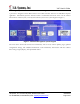
System Connections Overview
Figure 2: System Diagram
1. VAC: Vehicle Asset Communicator. User interface and intelligent industrial control device.
Operators read the display and use the keypad to interact with the vehicle control system. A two-
way radio transceiver is embedded within the VAC.
2. VAC-to-PCM Cable: Cable that connects the VAC to the vehicle’s Power and Control system.
This cable must route from the VAC mounting location (driver area) to the vehicle (typically the
engine/motor compartment).
Installation Summary
The installation must be performed in the order that follows:
Installing the VAC (with optional ID reader) [Items 1, 2]
Configuring the VAC using On-Screen Display
Before Starting the Installation
Before starting a VAC installation, make sure that all required tools and equipment and the Installation