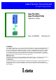
i-data Electronic Documentation The i-data Printing Solutions ida FS 250 / ida FS 250 PDS Operator’s Guide Doc. no D60256 Revision 03 WARNING: This equipment generates, uses, and can radiate radio frequency energy and if not installed and used in accordance with the instruction manual, may cause interference to radio communications.
ida FS 250, Operator's Guide Document No.: D60256-03 © Copyright i-data international a-s 1997 i-data international a-s Vadstrupvej 35-43 DK-2880 Bagsvaerd Denmark Telephone: +45 44 36 60 00 Telefax: +45 44 36 61 11 E-mail: i-data i-data.com WWW: http://www.i-data.com SUBSIDIARIES i-data Denmark Vadstrupvej 35 DK-2880 Bagsvaerd Denmark Telephone: +45 44 44 77 50 Telefax: +45 44 44 85 50 i-data Sweden Datavägen 21 S-43600 Askim Sweden Telephone: + 46 31 680710 Telefax: + 46 31 682670 i-data UK Ltd.
Table of Contents ida FS 250, Operator's Guide Preface September 1997 This manual applies to the ida FS 250 and the ida FS 250 PDS protocol converters. NOTE: Both products: “ida FS 250” and “ida FS 250 PDS” will be referred to as “ida FS 250” unless specific reference is made to the IPDS functionality of the ida FS 250 PDS. The ida FS 250 supports twinax Centronics and RS232 inputs. The default output is Centronics. The manual describes how the ida FS 250 is connected and oper ated.
Table of Contents ida FS 250, Operator's Guide As the ida FS 250 emulates the IBM 3812 printer in IBM 5219 emulation, useful information may be obtained from: "IBM 5219 Printer, Models DO1/DO2, Programmer's Reference Guide" IBM Order no. GA 23-1025 "Using the IBM Page printer 3812 with an IBM System /36 or System /38" IBM Order no. S544-3343 "AS/400 Device Configuration Guide", IBM Order no.
Table of Contents ida FS 250, Operator's Guide Table of Contents Preface................................ ................................ ................................ ....................... 3 Related Manuals ................................ ................................ ................................ . 3 Table of Contents................................ ................................ ................................ ...... 5 Kit Contents................................ .........................
Table of Contents ida FS 250, Operator's Guide 8.6 Quick Reference Guide of Supported FSL Functions ................................ 32 9. Programming via Shareport................................ ................................ ............... 43 9.1 Updating firmware ................................ ................................ ...................... 45 10. Errors and Recovery................................ ................................ ......................... 46 10.
Kit Contents ida FS 250, Operator's Guide Kit Contents Please check that your kit is complete with the following: ida FS 250 • ida FS 250 converter • Wall plug power supply • Parallel printer cable • Auto-terminating twinax T-cable • Product documentation (electronic format): ida FS 250 / ida FS 250 PDS Operator's Guide; Doc. no. D60256 • Product documentation (hardcopy format): ida FS 250 / ida FS 250 PDS Quick Guide; Doc. no.
Introduction ida FS 250, Operator's Guide 1. Introduction to ida FS 250 This chapter gives a short description of the ida FS 250 converter 1.1 Introduction to ida FS 250 The ida FS 250 is a protocol converter which enables any printer to be connected to an IBM computer system. See Section 1.3, Supported Control Units, for information on the IBM systems to which the ida FS 250 connects.
Introduction ida FS 250, Operator's Guide • Support of Automatic Page Orientation IPDS: IPDS support - IBM 4028 and 3812 or 3816 emulation. • Non-IPDS support via the installed i-data interface card, with full emulation of IBM3812/5219/3816 and IBM 5224/ 5225/5256/4234. • Support of the ida PSS software package • Support of the i-data Function Selection via the Line (FSL) facility in non-IPDS mode. • Automatic input sharing between Twinax, Centronics and RS-232 input ports.
Connecting to System ida FS 250, Operator's Guide 2. Installation Requirements Before connecting the ida FS 250, you should check the requirements described in this chapter. 2.1 Environment requirements The ida FS 250 protocol converter can be installed in the following environment: • Temperature range from 10 ° - 40° • Humidity between 8-80 %, non-condensing • Power consumption: 120 and 220 Volt version - max. 21.5 VA WARNING! The equipment must be grounded.
Connecting to System ida FS 250, Operator's Guide &&??% (defines % as temporary ESC character) %Y8,% (selects language) %X1 (saves setup) Changing Language via the Line Your can select between the following languages: Option 37 256 273 274 275 276 277 278 280 281 282 283 284 285 297 500 871 Description English (US) EBCDIC International Austrian/German Belgian Brazilian Canadian French Danish/Norwegian Finnish/Swedish Italian Japanese (English) Portuguese Spanish Speaking Spanish E
Connecting to System ida FS 250, Operator's Guide 3. Installation and Connections of the ida FS 250 This chapter starts with an overview of the functionality of the rear panel. Then follows a description of how you connect the ida FS 250 box to a printer and finally you will find instructions for connection to a system. NOTE: Before you start the installation, make sure that you set the address switch and the desired emulation. See the description in the section : Emulation. 3.
Connecting to System ida FS 250, Operator's Guide For this connection you need a spare cable ending in a 25-pole RS connector (i-data order no. 999010 030). Y24 = 0 is also To use the serial input, Function 24 Data Input/Output Port Select must be set used for to zero (which is factory default). Centronics output.
Connecting to System ida FS 250, Operator's Guide 3.2 Emulation As a default the ida FS 250 will emulate IBM 3812/5219/3816. The ida FS 250 PDS emulates IPDS as a default. You can select emulation in two ways. Either via the address switch or via the line using FSL function Y37.
Connecting to System ida FS 250, Operator's Guide Non-IPDS Selection *0 1 2 3 4 5 Emulation 3812 / 5219 / 3816 5224 5225 5256 4234 3812/5219/ 3816 * default value Matrix printers Selecting emulation via address switch 6. Connect the twinax cable and switch power on. 7. Activate the "T" position again and check that the emulation and address switch have been changed. (See the settings printout). See the section: Testing.
Connecting to System ida FS 250, Operator's Guide Y37,n1 Write 3812 5224 5225 5256 4234 Emulation *3812 / 5219 / 3816 5224 5225 5256 4234 * default value SCS printers Selecting emulation via the line The default configuration of the ida FS 250 can be used for most application programs and uses. You should only change the address and the emulation. The rest of the settings should only be changed if you have special requirements. 3.
Connecting to System ida FS 250, Operator's Guide 3.4 Connecting the ida FS 250 to the Printer CAUTION: All connections to theida FS 250 protocol converter should be made while the power is switched OFF to both the printer and converter. 3.4.1 Connecting via Centronics output Connecting the ida FS 250 to the printer is done by following these steps: 1. Check that the printer's parallel input port is available on printer. 2.
Connecting to System ida FS 250, Operator's Guide 3.4.2 Connecting via RS-232 output Note: This does not apply for the ida FS 250 PDS 1. To use the RS-232 port as an output por t you must set function Y24 to 1. (For further details on programming the ida FS 250, please see the chapter Programming ida FS 250). If possible, the serial output device you are connecting has to be set to Baud rate = 9600, Number of data bits = 8, No parity and 1 Stop Bit to match the default settings of the box.
Connecting to System ida FS 250, Operator's Guide If the printout format does not match the test printout in Appendix B. or if nothing was printed, this means that the printer setup does not match the protocol converter setup. Contact your systems support personnel or your i-data dealer. 6. Power OFF and ON the ida FS 250 and check that all indicators light up momentarily. 7. Proceed to the chapter: Connecting ida FS 250 to System. 3.5.
Connecting to System ida FS 250, Operator's Guide If all three (a. b. and c.) are in order, contact your systems support personnel or your point of purchase. 3.5.1 Testing The test printout pages can be generated in two ways - via the address switch or via the line activating the T function . For details on the T function, please see the section: Quick Reference Guide of the Supported FSL Functions. Test via the address switch 1. Turn the address switch to the "T" position.
Connecting to System ida FS 250, Operator's Guide 3.5.2 Timeout The ida FS 250 enables printer sharing between the system and a PC. For this purpose it is possible to specify a timeout period. If the printer is receiving input on the parallel port, for example, and there is a break in the transmission of data, the other input ports will not be polled for the period speci fied. The factory default timeout is 20 seconds . The timeout may be changed to suit your requirements.
Specifying Share Timeout and String ida FS 250, Operator's Guide 4. Operation of ida FS 250 The ida FS 250 top panel has been designed to register the operation of the box via the four following indicator LEDs : • CU (contact to control unit) • PAR (parallel input) • SER (serial input) • READY (printer) 4.1 ida FS 250 top panel CU The CU indicator has 3 states which signal the following: State ON BLINKING OFF Indication Contact with the control unit. In test mode.
Specifying Share Timeout and String ida FS 250, Operator's Guide SER (Serial input/output) The indicator LED has 3 states State ON BLINKING OFF Indication Indicates that the box is processing data from the RS232 Serial input Indicates that the box has defined the RS-232 as output for the box. Indicates that the box is idle or is processing data from the twinax/Centronics inputs.
Specifying Share Timeout and String ida FS 250, Operator's Guide 5. Specifying Share Timeout and String In order to specify the timeout for a specific input port, an FSL ( Function Selection via the Line) sequence must be sent to the port in question. To do this a temporary Escape (ESC) Character must be defined first. This is done in the following way: &&?? The sequence "&&??%" will define " %" as the ESC Character. Timeout is specified in FSL Function 100 .
Specifying Share Timeout and String ida FS 250, Operator's Guide %X1 NOTE: %X1 will delete the temporary escape character. The FSL string above was split up into several lines for reasons of clarification to simplify the explanation of the different functions. Below is an example where the FSL string is typed in one line.
IPDS Setup ida FS 250 PDS, Operator's Guide 6. idaSetup - IPDS Programming NOTE: This chapter only applies to the converter when mounted with an IPDS module. idaSetup is a program developed with the purpose of setting up the wide range of IPDS protocol converters via a PC share port or from a host. For details on how to configure the IPDS parameters for the ida FS 250 PDS using the program idaSetup, see the separate documentation for this, “IPDS Programmer’s Guide”, doc. no. D60253.
Programming ida FS 250, Operator's Guide 7. IRQ Handling This section describes how to recover from various IRQ conditions. • • • Paper jam Out-of paper Stacker full The printer will recover from these conditions without loss of data as long as you do not power off the printer. • Printer Not READY The ida FS 250 PDS will detect if the printer is NOT READY and will interrupt data transmission to the printer. If the printer is OFFLINE (i.e.
Programming via Shareport ida FS 250, Operator's Guide 8. Programming ida FS 250 - non-IPDS The ida FS 250 works using a large number of internal Setup Functions (FSL Functions). FSL setup functions can be sent either from your IBM system or from a PC. When the protocol converter has been installed and connected to a printer, you may have to consider the use of these setup options.
Programming via Shareport ida FS 250, Operator's Guide 8.2 Defining a Temporary Escape Character The ESC Character may be defined as a temporary as well as a permanent ESC Character. Below see how to define "%" as a temporary ESC Character. &&??% Defining "%" as a temporary ESC Character . Since the temporary ESC Character is defined in the temporary memory (RAM) alone, it is only in effect as long as the printer is switched on - or until you remove it again. To remove it you define it as "space".
Programming via Shareport ida FS 250, Operator's Guide 8.5 Setup Functions supported (PCL Mode) No.
Programming via Shareport ida FS 250, Operator's Guide No. Description X Save/Overwrite Settings X1 Store Settings in Permanent Memory X3 Restore Factory Default Settings X4 Restore Settings from Permanent Memory Send User String Send User String Send Bar Code (as defined in Y59) Program Flash Prom Z S W P ESC Features: %% Special transparent feature (Multiple paired Hex transparent). e.g.: %%1B45% where % is the defined ESC character. % Special transparent feature (Single paired Hex transparent).
Programming via Shareport ida FS 250, Operator's Guide 8.6 Quick Reference Guide of Supported FSL Functions In this section the supported FSL Functions in twinax will only be described with their syntax and parameters.
Programming via Shareport ida FS 250, Operator's Guide No. 2 Name LPI Syntax %Y2,% 3 CPI %Y3,% 8 Language %Y8,% Parameters 3 = 3 LPI 4 = 4 LPI *6 = 6 LPI 8 = 8 LPI 5 = 5 CPI *10 = 10 CPI 12 = 12 CPI 15 = 15 CPI 16 = 16.7 CPI **37 = Engl.
Programming via Shareport ida FS 250, Operator's Guide No.
Programming via Shareport ida FS 250, Operator's Guide No.
Programming via Shareport ida FS 250, Operator's Guide No.
Programming via Shareport ida FS 250, Operator's Guide No.
Programming via Shareport ida FS 250, Operator's Guide No. 51 Name User-Defined String(s) at Power-Up Syntax %Y51,% 59 Bar Code Type Definition %Y59,,, ,[,n5]% Parameters 0-7 = One or more strings stated in the form: (n1),(n2) ,....(nx) in ascending order The strings must be predefined in FSL 61 n1 Numeric value from 1-8 specifying the bar code no.
Programming via Shareport ida FS 250, Operator's Guide No.
Programming via Shareport ida FS 250, Operator's Guide No.
Programming via Shareport ida FS 250, Operator's Guide No. 91 Name Font Definition Syntax %Y90,,, ,, [,n6]% See Appendix D. for more details on fonts Parameters n1 (IBM GFID) 1-65535 = IBM GFID no. n2 (Typeface) 0-255 = Pre-programmed typeface value n3 (Attribute) 0 = Remove all current attributes 1 = Bold 2 = Italic 3 = Bold and Italic 4 = Proportional 5 = Prop. Bold 6 = Prop. Italic 7 = Prop.
Programming via Shareport ida FS 250, Operator's Guide No. 94 96 97 Name Font Typeface Definition String Font Change Simulation See Appendix D for details on scalable fonts GFID/Font Selection Syntax %Y93,,% Parameters n1 10-255 = String no in decimal %Y96,% n2 00-FF = String contents in HEX 1-65535 = GFID no. %Y97, n1>,:% n1 1-65535 = GFID No.
Programming via Shareport ida FS 250, Operator's Guide No.
Programming via Shareport ida FS 250, Operator's Guide 9. Programming via Shareport In order to ease customization of the ida FS 250, FSL parameters for twinax input can be programmed directly via the interface's Centronics or serial (RS-232) port using the Engineering Function Y249. The Engineering Function enables the system to detect whether FSL sequences on shareport are intended for twinax FSL input or for shareport setup and will direct the sequences received to the twinax FSL interpreter.
Programming via Shareport ida FS 250, Operator's Guide If you have defined % as Escape Character, you activate the engi neering function by typing: %Y249,n% n = password. As this is sensitive information, system operators can contact point of purchse for password details. Deactivating the Y249 Engineering Function The function will be deactivated automatically after timeout on the share port (timeout is defined in Y100 Port Sharing Option). See also the chapter: Specifying Share Timeout and String.
Error Messages ida FS 250, Operator's Guide 10. Errors and Recovery Printer-related error messages will be displayed on the printer front panel. To recover from these errors, please refer to the relevant printer documentation. The following errors are related solely to the ida FS 250 and will appear as printed error messages. For some of the error messages, additional explanatory text may be printed out together with the error message. 10.
Appendix Section ida FS 250, Operator's Guide Appendix A: Use of ida FS 250 Serial Port The following connections are available in the serial plug: pin 1: pin 2: pin 3: pin 4: pin 5: pin 6: pin 7: pin 8: pin 9: N.C. RX data TX data DTR GND (signal) DSR (busy) RTS (always high) N.C. N.C.
Appendix Section ida FS 250, Operator's Guide Appendix B: Test Printout ida FS 250 Firmware version: S20 140.010/00970005 i-data international a-s Vadstrupvej 35-43 2880 Bagsvaerd, Denmark Phone: +45 44366000 Fax: +45 44366111 Boot id: 80023102 HW id: Current escape code = 00 in hexadecimal as Character = ' ' Dipswitch: National character set = Multinational Line Set Up: Addr. 0 3812 model 1.
Appendix Section ida FS 250, Operator's Guide Appendix C: Default GFID Table The factory default GFID Table below lists all the predefined fonts which are supplied with the interface GFIDs (GFIDs 1 - 399) 2. Fonts with GFIDs above 400 (i.e. scalable fonts) are described in the section Scalable Fonts below. For further details on defining fonts, please see the section: Quick Reference of Supported FSL Functions, Function Y91 and Y96.
Appendix Section ida FS 250, Operator's Guide In the table below, an asterisk (*) after the GFID number denotes a simulated IBM GFID.
Appendix Section ida FS 250, Operator's Guide Scalable Fonts NOTE: Only applies to printers running PCL Level .5 The ida FS 250 allows GFID access to all the scalable fonts found in the printer. These GFIDs are in the range 400 - 65535. Typeface, typeface attributes and point size have been linked together using the system described below. GFID Number = XXXYY where XXX = point size and YY = typeface + attribute Possible typeface values are: Typeface ID 0 4 10 14 20 24 30 34 40 44 50 54 60 PCL No.
Appendix Section ida FS 250, Operator's Guide %Y96,4815% This is 48 point, Helvetica Compressed, bold upright %Y96,1301% This is 13 point, Times Roman, bold upright Font examples Other relationships between IBM GFID and printer typefaces/fonts can be programmed using Function 91 or 97 (See Programmer's Guide for more details on Function 97). GFIDs may be selected with the normal procedure or using Function 96.
Appendix Section ida FS 250, Operator's Guide Appendix D: i-data Product Platform Coax ida LS 170 ida LS 270 ida FS 270 ida FS 270 PDS ida PDS 270x MIO ida PDS 270x Optra Twinax ida LS 150 ida LS 250 ida FS 250 ida FS 250 PDS ida PDS 250x MIO ida PDS 812-1x Optra S/370 - 390 External S/370 - 390 External External S/370 - 390 External Internal Internal AS/400 External AS/400 External External AS/400 External Internal Internal SCS For Centronics attached matrix printers SCS + AFP For Centronics attached la
Appendix Section ida FS 250, Operator's Guide Token Ring ida PS 03 TR ida PrintServer 03 IOP TR ida PrintServer 03 MIO TR ida PS 03 NP TR ida PS 23 TR 270 ida PrintServer 23 IOP TR 270 ida PrintServer 23 MIO TR 270 ida PS 23 NP TR 270 ida PS 23 TR 250 ida PrintServer 23 IOP TR 250 ida PrintServer 23 MIO TR 250 ida PS 23 NP TR 250 ida PS 13 TR ida PrintServer 13 IOP TR ida PrintServer 13 MIO TR ida PS 13 NP TR Ethernet ida PS 04 ETH ida PrintServer 04 IOP ETH ida PrintServer 04 MIO ETH ida PS 04 NP ETH ida
Index ida FS 250, Operator's Guide Programmer's Guide, 28 Index —Q— Quick FSL Reference Guide, 32 —S— —C— Scalable Fonts (Typographic), 51 Shareport Connections A/B Switch, 13 Address Switch, 13 Parallel In, 12 Parallel Out, 12 Serial Port (Out), 47 Serila (In/Out), 12 Twinax Connector, 13 Activating Y249, 44 Deactivating Y249, 45 Programming via, 44 —T— Testing Control units, 9 Via address switch, 20 via function T, 20 —D— Timeout, 21 Specifying, 24 Default FGID Table, 49 —E— Emulation, 13 V
Reader's Comments ida FS 250, Operator's Guide READER'S COMMENTS This manual is part of a library that serves as a reference source for programmers and operators of i -data equipment. This form may be used to communicate your view about this publication. Your in terest is appreciated. Comments may be written in your own language, use of English is not required. Documentation i-data international a-s Vadstrupvej 35-43 DK-2880 Bagsvaerd Denmark or use our E-mail address at the Internet: i-data i-data.