
User's Manual


10
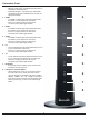
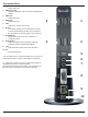
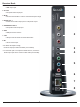
Remote Control
1. POWER ON Button
• Turns the Transmitter and Receiver power ON
2. POWER OFF Button
• Turns the Transmitter and Receiver power OFF
3. INFO/OK*
• Displays the following information on the screen:
Transmitter - WiFi IP, LAN IP, and Source
Resolution.
Note: The Transmitter unit’s information will
only be displayed if the connection between the
Transmitter unit and Receiver has been
established.
Receiver - WiFi IP, WiFi Channel, LAN, SSID,
Display Resolution, WiFi Reception Strength.
*Displayed information will disappear automatically after
30 seconds.
4. VIDEO OUT (Receiver)
• Selects the Audio/Video output port of the Receiver.
HDMI - Selects HDMI as the Audio/Video output.
Component - Selects Component as the
Audio/Video output.
AV - Selects AV as the Audio/Video output.
Note: Remote must be pointing directly at the Receiver to
control its output settings. This may also be accomplished
without the use of the remote control by toggling between
outputs via the Link/Output Selection Button on the
Receiver.
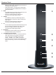
5. VIDEO IN (Transmitter) - Selects the Video input port of the Transmitter.
• HDMI1 - Selects HDMI1 as the Audio/Video input.
• HDMI2 - Selects HDMI2 as the Audio/Video input.
• HDMI3 - Selects HDMI3 as the Audio/Video input.
• PC - Selects VGA/Component as the Audio/Video input.
• AV - Selects Composite as the Audio/Video input (requires included
Component/Composite adaptor).
6. Scan
• Selects Scan/Pairing mode. System will re-scan among 10 possible WiFi frequencies and select the optimum available
channel. The channel selected will be displayed when “Info” is pressed.
7. MENU and DOWN, RIGHT, LEFT Buttons
• Disabled - for future use.
8. UP Button
• This will scroll through the possible IR frequencies. This device accommodates most IR protocols in use today. To do
so it will require selecting the one of four possible carrier frequencies available for IR control. Press the UP arrow to
scroll between 31 KHz, 38 KHz, 47 KHz and 57 KHz frequencies.
• Select a frequency and try your source remote. If the control responds, then you have selected the correct one. If the
device does not respond, try another frequency. If no frequencies seem to work, ensure the IR emitter is located in the
correct location on the source component.
POWER POWER
RECEIVER TRANSMITTER
FFONO
MENU
SCAN
/ BACK
INFO
/ OK
HDMI HDMI1
COMPONENT PC HDMI2
AV AV HDMI3
1
7
4
2
6
5
3
8
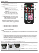
Remote Control Battery Installation And Replacement
The battery clip is located on the bottom of the remote control.
Battery ClipTab
123
Push the tab, located on the left of the battery clip, to the
right and pull out the clip.
Place the battery into the clip, positive (+) end facing up
as shown.
Place the clip back into the remote to complete the
installation.
1.
2.
3.