Table of Contents About This Guide ------------------------------------------------------------------------------------------------- 4 FCC Compliance Statement ------------------------------------------------------------------------------------ 4 FCC Warning ------------------------------------------------------------------------------------------------------ 4 License Agreement ------------------------------------------------------------------------------------------------ 5 Trademark ---------------------
4-11. Storage configuration ------------------------------------------------------------------ 95 4-12. Public address configuration -------------------------------------------------------- 100 4-13. Control Panel -------------------------------------------------------------------------- 106 Chapter 5. Accessory Programs------------------------------------------------------------------------------111 5-1.
About This Guide Conventions used in this guide to make sure that you perform certain tasks properly, take note of the following symbols to use throughout this manual. WARNING: Information to prevent injury to yourself when trying to complete a task. CAUTION: Information to prevent damage to the components when trying to complete a task. IMPORTANT: Information that you must follow to complete a task. NOTE: Tips and additional information to aid in completing a task.
License Agreement Notice to end-user: please read the following legal agreement carefully. Use of the Witness or any of the software provided with this agreement constitutes your acceptance of these terms. If you do not agree with the terms of this agreement, PROMPTLY RETURN the Witness system, Witness, AnyView Pro and FreeView Pro , any related software and the included items (including the Witness video system, written materials and containers) to the location where you purchased them for a full refund.
party rights. If law does not permit such disclaimer of any implied warranty, the duration of any such implied warranties is limited to 90 days from the date of purchase. Some countries do not allow the disclaimer of implied warranties, limitations on how long an implied warranty lasts, or the exclusion or limitation of incidental or consequential damages, so such limitation as or exclusions may not apply to you.
Should you have any questions concerning this Agreement, please contact I-View directly at one of the numbers or addresses listed at the beginning of this manual. Trademark DigiCap II, DSecu, AnyNet, e-Witness, AnyNetPro, u-Witness XP, x-Witness, FreeView Pro, AnyView Pro, PDAView and MobileView are registered trademarks of I-View Communication Inc. Microsoft, Windows 95, 98, ME, Windows2000, XP, Vista and 7 are registered trademarks of Microsoft Corporation.
Chapter 1 Product Introduction 1-1. Model Description Model AnyNet-3208 Description 32 channels I-View’s IP devices and/or 32 channels third-party IP devices digital video recorder provide 8 hot-swap SATA drive bays up to 32 TB HDD capability (4TB *8) with Raid 0, 1, 5, 10 functions. Has option of redundancy Power supply and 4/6/8 monitors display.
1-3. Recommend HDD List Seagate Model ST3000VX000 3TB SATA 6 Gb/Sec. ST2000VX000 2TB SATA 6 Gb/Sec. ST1000VX000 1TB SATA 6 Gb/Sec. WD1001FALS 1TB SATA 3 Gb/Sec. WD1002FBYS 1TB SATA 3 Gb/Sec. WD2002FYPS 2TB SATA 3 Gb/Sec. WD2003FYYS 2TB SATA 3 Gb/Sec. WD30EZRS 3TB SATA 3 Gb/Sec. Western Digital Model 1. The most 7200RMB SATAII/III HDD can capability with NVR. You can all your local dealer before buy the HDD. 2.
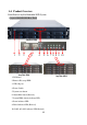
1-4. Product Overview Front Panel of AnyNet Embedded NVR System Anynet-3208/6416/6424 Rear Panel AnyNet-3208 1 2 3 3 4 5 6 7 8 8 9 10 AnyNet-3208 AnyNet-6424 1. DVD drive 2. Remove Hot swap HDD 3. USB 3.0 ports 4. Power Switch 5. System reset button 6. Alarm Mute button (Revised); 7. System HDD Activity indicator LED 8. Power indicator LED 9. Failed indicator LED (Revised) 10.
Anynet-3208/6416/6424 Back Panel 11 AnyNet-3208 1 2 3 4 5 6 7 8 9 10 12 13 AnyNet-6416 14 AnyNet-6424 1. Power supply: The power supply can be selected optional redundancy power supply. 2. Supplied power cord: Connect one end to the AC input. 3. Power switch: Turn on/off power supply. 4. PS2 keyboard/ mouse combo port: This port is for a PS2 keyboard/mouse. 5. USB port: For USB device plug in. 6. HDMI port: This port for HDMI monitor. 7. S/PDIF port: Audio output port.. 8.
Chapter 2. Hardware Installation Please use the HDD which supports 7200 RMP or above and the same model when you use the Raid 5 or 6 mode. Install Hard Disk Drive ① Remove protect tray from the tray. ② Insert the HDD on the tray. ③ Attach with 4 screws to fix HDD. ④ Push the lever to latch HDD tray. Remove Hard Disk Drive ① Pull the lever to latch HDD tray. ② Slide tray from HDD tray. Remove top cover of NVR ① Release two screws on the back side and twp screws on both left and right side.
2-1. How to Build up the Raid HDD To build up the new Raid HDD on the AnyNet NVR follow the steps shown as below: Step 1. Click button from Control panel to enable the Raid setting diagram. Step 2. Entry the User name and Password. The default is RAID/hpt. Step 3. Click “ Array type” icon to select the mode and Click “Quick Init” icon from Initialization Method section. Step 4. Check HDDs which you want to create the Raid function, then click “ Create “ icon to start.
Step 5. Click “ “ button from Control panel the diagram of HDD setting will pop up as below. Move the Mouse to “Format“ icon and then right click of Mouse, then check “GPT” section and click “OK” start to format the HDD. Step 6. Click “ New Simple Volume “ icon, then click “ Next “ icon. Step 7. Specify volume size which you want to the format for the HDD.
Step 8. Assign drive letter or path. Step 9. Format HDD partition; you can refer the setting as diagram setting as right side. Step 10. Click “Finish” button to finish HDD format.
Chapter 3. NVR Operating System After user finish the CPU, RAM and HDD installation, please remember to go to the system Control Panel to configure the NVR system for installed hardware devices operating properly. For detail about the setup NVR system configuration in control panel, please refer to chapter 3-1 NVR systems Control Panel Configuration. NVR System Main Screen Take note of the following precaution before you start to configure the NVR system. 1.
3-1. NVR System Control Panel Configuration Once user has finished the HDD installation, please click the Control Panel icon ( ) from the right side bottom corner of the NVR system main screen to configure the NVR system.
Control Panel Function Description: File Explore – To select the folder or file. Device Manager – To check the device driver. Setup Network Connections– To setup the system network configuration. Display Properties– To setup the system monitor display. Disk Management– To format hard disk when you install a new hard device. Setup Network Firewall– To setup the firewall to protect your NVR. Command Line – To enable DOS mode to run the command line process.
Set up password– Allows you to setup a password to secure the system parameters of the NVR. Set up password to access the control panel. Set up password for shutdown the NVR system. Fig. 3-1.
3-2. NVR Main Program 3-2-1.
3-3. Program Overview 3-3-1. The main function description: Video parameters setup - ezSetup: Enable/disable individual audio/video channels and configure the audio source and video resolution settings. NVR Surveillance Server – AnyNet: It is the main NVR application software program that provides on-site live video viewing, scheduled or motion triggered video recording, and much more.
Text insert playback - ezTextPlayback: Playback the recorded video clips with text transactions. You can search the video by text record or keywords, such as date/time, register, goods or amount. Please refer to PTI-100 or FAC-500 Operation Manual . Video files archiving - ezBackup: Share or back up your recorded video clips into other storage devices, such as a HDD, CD/DVD drive, USB Flash drive, Zip drive, etc..
Technology) along with the HDD’s own inner sensors can detect physical weaknesses of the hard disk drive. Our ezHDDSmart software program will report the HDD’s current health status, disk reliability, failure prediction and related statistical information. Please refer to chapter 5-6 for in-depth details. Fingerprint Access Controller – ezFingerKey: Manage the system configuration and the function usage for fingerprint access controller.
3-3-2. Video parameters setup Please click icon on the main screen or click to display the Video Parameters Setup window. This setup window may differ greatly depending on your NVR model. See the instructions below to modify the default settings. 1. Surveillance software control panel setup: The user can change the positions (either left or right of the screen) of the control panels in the Witness Pro Application.
2. Register Code: You can connect to IP camera by Mac ID registration. This is an optional function. Please contact your vendor for the license code shown as below. These settings must match with the setup of IP camera. Inform the MAC ID and get the code from your vendor a. Click “Register code” and inform the “MAC ID” for your vendor to get the code. b. Fill the code and click “Register’. After registering, the number of supported IP cameras will be shown on “Port” area. c.
3. Setup the parameters of IP camera Fig A Fig B Disable channel: This will disable the selected channel when enable this function. Install video codec: Install the video codec of this IP camera when you connect IP camera at first time. Vendor & Model: Select the correct brand and model for the connected IP camera. You also can select “Onvif” if your IP camera support Onvif compliant and not on the list.
used camera support Onvif compliant from: http://www.onvif.org. Click “ Onvif setup “ icon to setup the parameters or entry RTSP command code directly which you want to run on the Hybrid NVR or NVR. Compress: Select the suitable codec for video recording and transmission. Recording resolution: Select the resolution for video recording and display. Frame rate: Select the frame rate for video recording and display. Rate Control: You can choice video quality or bit rate from this tab.
The difference IP camera brand has its own “Find” and “Advance setup” setup diagram and setting process. For the detail information, please refer to the IP camera operation menu. HTTP port & RTSP port: The both port number must be matched the setting of IP camera which you want to connect.
Chapter 4. NVR Software Operation This chapter describes the functional aspect of the Witness Pro software application. 4-1. Surveillance Server (Witness Pro) The surveillance server is the primary application program of the I-View NVR systems. It provides comprehensive CCTV security solutions, including live monitoring, video recording, motion detection, alarm notifications, E-map for easy site management, events logs, schedule recording, remote surveillance connection via WAN/LAN/Internet/Intranet, etc.
Surveillance Server Functions Descriptions: 1. Login/Logout Button : You can log out as one user and log in as another with different privileges. The default username is “root” and the default password is “123”. This default user has full privileges. 2. Exit Button : Exit Witness Pro program. If a crossed-hand icon appears instead, you must first log out and next log in as a user with exit privilege. 3. Minimize Button : Minimize this program into the taskbar.
are three categories including “System configuration”, “Video display configuration”, “Connection ezDispatch Server setup”, “Save / Load configuration”, and “ezTools”. 11. User access setup : Manage a list of users with different access privileges. 12. Application logs : Review the user logins/logouts, motion detection records, video loss occurrences, remote user accesses, hard disk failure events, etc. 13. Peripherals setup : Set up new NVR peripheral devices for advanced system integration. 14.
recording sessions would not be affected. Announce: Allow announcing to this camera directly when the user need to announce information for cover area of this camera. This function just effects when the NVR connects the Public address server or this camera is IP camera type. Audio input from: Choice the audio input from the Sound card if installed more than one. Speak voice format: Select speak out voice format. Transform voice format: Choice different compression format for the audio converter.
PTZ: Press this icon allows using the Mouse to control PTZ cameras for the Pan / Tile / Zoom function from image directly. The process is described as below: Click the right button of Mouse and press the “PTZ” icon to control PTZ (Pan / Tile / Zoom) function from image directly and click the icon again to disable. Move the Mouse to the video of PTZ camera which you want to control.
selected video channel’s live images. Default: Bring back to the original settings. Swap with: Swap the on-screen positions of two different video channels. For example, if you wanted channel #1 to appear at position #15 and vice versa. Exit: Click this button to exit the video tools window. Snapshot: Take a single picture of the selected channel’s live image and save the snapshot picture in the disk.
Use Fisheye IP camera for 360°/180° Panorama viewing: The Witness Pro software provides the 360°/180° Panorama viewing function for our fisheye IP camera (FE-5MIP-F01). To access the Panorama video tools, move and right click the Mouse on the currently displayed video channel of Fisheye IP camera to bring up a small window shown as the right picture. Click “Panorama video setup “ icon you will find out the setting parameters. There are multi modes video displays for difference application.
4-2. Logging in the Surveillance Server To log in as a user, click the button from the top-right corner of the Witness Pro surveillance program. You can also change the username and password when you login. To log out, simply click the same button. The default login username and password are “root” (lowercase) and “123” respectively. That default login profile may be interchanged with your own (recommended).
4-3. Camera configuration 4-3-1. Camera configuration: General: This menu tab is primarily used to set up the OSD options (which text overlay to show in the videos) and name the locations of the installed cameras. To access this setup section, simply click the “General” tab at the top from the “Cameras configuration” window. Camera selection Select if display camera information in playback clips or live vido & playback clips. Type camera location and select the type and view direction of the camera.
Recording: This menu tab is primarily used to set up the video & audio recording functions. To access this setup section, simply click “Recording” tab at the top of the “Cameras configuration” window. Camera selection Activate the recording schedule. Set up video recording schedule. selection Activate audio recording. This function is only available with audio capable NVR models. Set up as a maximum video streaming file size determined by minutes or hour.
motion recording” as well to record continuously no matter the motion is triggered or not. Hybrid recording: Record high frame rate only upon motion detection and non-stop recording with slow frame rate without any triggered. You can select the frame rate from “No motion recording” tab as well to record continuously no matter the motion is triggered or not. Using this recording mode can save the HDD capability without losing any video clips.
Section 2: Type: The user can set up recording schedule for “Daily”, “Weekly” or “Special duration”. Start time & End time: Set up time frame for recording schedule. Here’s a classic sample recording schedule: “motion triggered recording” from 00:00 to 07:59; “continuous recording” from 08:00 to 16:59; “motion triggered recording” from 17:00 to 23:59. You should always set your complete schedule start at 00:00 and end at 23:59.
Section 5: The Witness Pro NVR system provides intelligent video detection functions and the description as below: Motion setup: The user will be fine-tuning how the NVR starts recording if people or objects are moving in the angle of view. To access this section, simply click “Motion setup” from “Select detection” drop bar. There are “Software detection” and optional “Hardware detection”.
Areas Setup – Select or frame the specific areas from the view of the camera for motion detection. To add a new area of detection, please follow the steps shown as below: Step 11. Flame and drag on the video image to select the desired detection area by your mouse. Step 12. Click button to add the new selection. Step 13. To set up others detection areas, repeat step 1 and 2. Step 14. Choice the sensitivity level for the detection.
The system allows detecting the illegal parking, please following the steps shown as below to process of detection illegal parking. Step 1. Choice “Illegal parking” item from “ Select detection” drop box. Step 2. Setup the parameters for illegal parking detection. • Choice the sensitivity level for the detection from 1 to 5 (1: Lowest; 5: Highest). • Select the speed of buildup background. • Choice “Scene change level” to suit for application area.
Section 6: Alarm Tolerance – You can define the acceptable movements to prevent false alarms movements. For example, if the tolerance is set to 2, the movements in the video must be occurred at least three consecutive times to trigger alarm and start to record this video channel. Post recording – You can set the duration to continue recording after motion is no longer detected.
Enable Pop up video: (For Hybrid DVR only) Enable alarm siren: The NVR can sound an alarm upon motion detection. Make sure your NVR is equipped with a pair of PC speakers. Click button for setup. Enable notification: Notification by phone call, SMS message, email notifies, upload to FTP server and live videos transferred to a remote site PC when motion detection is triggered.
at the remote PC; otherwise the connections will be failed. Please note you also need to open from your router configuration for remote PC. Check your router manual for more info about “port forwarding” or “virtual server”. Notify by Email: Upon motion detection, the NVR system will automatically send e-mail messages to the registered email recipients. Please follow the steps below to set up e-mail notification entries. Step 1. Click “E-mail message” tab. Step 2.
stamp. Please follow the steps below to set up FTP server notification entries. Step 1. Click “FTP notify” tab. Step 2. Enter the DNS name and port number (default is port 21) which the user wishes to send the triggered information to this FTP server. Step 3. Entry the “User name” and “Password” of FTP server for login. Step 4. Enable “ Passive mode” for some special FTP server. Ask your MIS staff for the detail setting. Step 5. Entry the saving path and check “Attached image file” icon, if you needed.
Step 10. Click “Sound File setup” button to choose an alarm siren or to record your own voice message. Step 11. Click “Save” button to save your pending entry. This entry will be listed at the bottom section of this window. Step 12. Repeat step 2 through 4 to add other phone call notification entries. 1. If the user would like to record his own voice message, the “.WAV” file format must be 8000Hz, 16-bit and Mono for phone call notify. 2.
Step 3. Type the SMS message. Step 4. Click “Save” button to save your pending entry. That entry will be listed at the bottom section of this window. Step 5. Repeat steps 2 through 5 to add another SMS message notification entry. You must use an approved 3G Modem for sending SMS message to mobile phone. Shift PTZ position: Upon motion detection, the PTZ camera can automatically move to the aiming position(s) of one or more or whatever the preset position(s) the user has defined.
Record/Play alarm Plays chime sound sound file before alarm voice Browse /Select the existed sound file Adjust alarm voice List selected alarm volume sound files Select announcement List selected zones area by zone and and groups group Step 1. Choice “Zone” and “Group” where will announce when NVR is triggered. The detail setting process of “Zone” and “Group”, please refer to “Public address configuration” chapter. Step 2.
Video Loss The NVR can send an alarm or other kinds of notifications if there is any video signal loss from the camera; either due to the problem of power supply or bad video coaxial connections.
occurred on this camera. Enable notification: Each camera can have its own unique setup for notifications when video loss occurred. Shift PTZ position: Set one or more of your connected PTZ cameras to move for one or more preset positions when video loss occurs on this particular camera. Trigger output relays: Select the output relays from Relay 01 to 13 in “Controller board” (NC-3213USB) or select the output relays from each NC-180AZ PTZ receiver module when video loss occurred.
Font: Click Clear: Click icon to specify the font size of text on the video clips. icon to erase the POS text shown on the current monitor. Text data show on “Monitor + Video clips”: Enable to display the text from POS or Access Controller on the connected monitor, video clips and remote PC. Please go to “General” tab and select “Monitor+clips” from “Shown on” to enable this function. After selecting “Monitor+clips”, all this function will be automatically selected.
“Always” or “Never” to determine if the status of inserted text.\ 6.) Keep text records: Setup the retained period for text. This text record will be shown on the “Text insert Playback” and used for searching text on videos. 7.) Enable video recording when transaction starts: The NVR will start to record when the transaction starts and specify the recording duration when the transaction stops. 8.
4-4. Video playback / Synchronized playback / Text insert playback / ezBack 4-4-1. Synchronized playback 1 2 10 3 9 4 8 7 6 5 Function descriptions of Synchronized playback: 1. Split screen display modes section: Select the split screen display mode 2. Camera selection of the video clips: Select the playback cameras from the selected video clips folder. 3. The video clips deletion: Delete the video clips from the hard drive. 4.
clips. 7. Video stream searching bar: 0~23 (Hours) selections: Search the video stream data by hours. White/Gray color video stream blocks: White color block indicates empty data, and gray color block indicates video data. 0~60 (Min) dragging bar: Search the video steam data by minutes. 8. Playback speed selection: Provide user to select the playback speeds for easily searching. 9. Video stream information: Display the selected video steam information. 10. Display screen: Display the video.
Resize – Resize the video clip. Decrease frame rate – Decrease the frame rate. Normal frame rate – Adjust frame rate back to normal. Increase frame rate – Increase the frame rate. Screen size can be adjusted by selecting different multiple displays. Click to view videos in 352 x 288; click click view videos in 160 x 120. to view full screen; to view videos in 176 x 144; click to Smart search video: Mark the objects in a selected region for searching in a recorded video clips.
Step 3. Click “Add area” button to save a highlighted region. The user can use the same way to add more areas. Step 4. Adjust “Sensitivity”, “Speed”, and “Range” function, and click “Search” button to start the smart search function. Step 5. The system will display all detected object change events on the right list window, and the user can select an event to playback. Basic operation of synchronized playback 1.
4-4-2. Video playback At the playback screen, you can play back videos. Double click on any video screen to enlarge a single video. Move the mouse to any video screen to show video tool bar and information of single video. Double click again to restore the previous viewing screen. Previous video clip – Jump to the previous video clips. Next video clip – Jump to the next video clips. Navigation bar – Display the current position of the video clip and allow users to move to different points within the clip.
procedure for setting the desire point of end frame. After saving the desire point for “Start frame” and “End frame”, the set up record will automatically send to “Merge file(s)” setup field. The user can set up “Start frame” and “End frame” for each video clip. Decrease speed – Decrease the speed of playback. Normal speed – Adjust the playback speed to normal. Increase speed – Increase the speed of playback. Play – Play video. Pause – Pause video. Stop – Stop video.
Audio Volume – Adjust the audio volume of the playback video clips. Smart search video – Search the playback video clips by marking a specified areas or regions. Please refer to the 4-4-1 Synchronized playback for the detail description of “Smart search video”. Merge file(s) – Merge the different files from the different video clips and export as one “.AVI” file. Please follow the introduction below to perform this function. 1 2 3 4 5 7 6 8 9 Function descriptions: 1.
6. Show the time frame and frame number for the selected start frame. 7. Show the time frame and frame number for the selected end frame. 8. Show the list of selected video clips which would like to be merged as one “.AVI” file. 9. Select the location where the user would like to save the file and click “Merge file” to save the file. Follow the steps below to merge the files: Step 1. Select the desire video clip. Step 2.
Repeat – Repeat all selected playback video channels. Search video clips – Playback the videos via a single or multi channels. Follow the steps below to play back videos: Step 1. Click to search for video chips in the database. Step 2. Select the camera from the drop-down menu. To play multiple videos, select “All cameras”. If selected all cameras, there will be a “Select cameras” pop-up window for camera selection after clicking “Search”. Step 3.
Delete video clips – Playback the videos from a single or multi channels. Follow the steps below to remove a video clip from your archive: Step 1. Click on right screen for deleting video chips. Step 2. Select a single camera or all cameras to delete video chips. Step 3. Select “All clips”, “scheduling”, or “motion detection” from “search by” drop-down menu. Step 4. Select the search method from “Options” field. Step 5. If you select “All video clips”, click “Delete” to delete the video clips. Step 6.
4-4-3. Text insert playback The user can playback the videos with text when the NVR integrated with POS system or fingerprint access controllers. Please refer to the PTI-100 user manual of POS system and FAC-500 user manual of fingerprint access controller for hardware installation, system configuration and functions usage. 2 1 5 3 4 The text data will be shown here. You Please refer to the chapter 4-4-1 for detail of toolbar functions can click any text data to display the video in the left side.
Step 3. Click any video clip to display and playback in the left side. Please note some video clips might not contain any text data if there is no text transaction in this specified time. Step 4. All the transaction text will be shown on “Text record” tab. You can simply click any text data to display the video from “Text record” tab, search the video clip from “keyword” tab, or type any words from “Search” tab to search the video clips. Step 5. You can also un-check “Use default” and click folders.
4-4-4. ezBackup This chapter will show how to back up video clips to another storage device. Function description of ezBackup: Search – Search video files. Select – Select/Deselect all video clips for back up video clips. Create backup shortcut – Create shortcut of selected backup videos for the other storage devices; such as CD-RW/DVD+-RW. Back up video clips – Back up video clips to Hard Disk. Setup auto backup schedule – Backup video clips to Hard Disk by schedule automatically.
Step 6. Select video files which you would like to backup by manual. Or you also can click to “Select all/Deselect all” video files. Step 7. The ezBackup program provides three methods to backup the video clips and the detail process are shown as below: Backup to another HDD by manual: a. Click to show “Back up video clips” window. b. Check “copy playback program” if you would like to playback with Witness playback program.
up “ezPlayback” and “Synchronized playback” program at the same time c. Select the HDD from “Storage drive“. d. Click “Start” icon to start backup. Setup auto backup Schedule: a. Click to show “Setup auto backup schedule” window. b. Select “Enable Auto-backup schedule” function. c. Select the date to backup video clips from “Backup date from” field. d. Select “Recycle” or “Stop backup” when backup HDD is full. e. Select the backup schedule from “Daily“, “Weekly”, “Per hour(s) “, or “Only Previous day”.
warning level and setup the notification method from “Advance”. Please refer to Chapter 3-3-1 (Camera configuration Recording Schedule setup) for detail setup instructions. i. Set up for “Second notify to CMS when backup HDD less than” if needed. Backup video clips from DVD+-RW (CD-RW): a. Click to show “CD/NVR Burning” window. b. Insert the backup media such as CD or DVD disk. c. Select the correct “Device” and “Media type”. d. Click “Burn now “icon to start backup.
4-5. Remote Access setup This section will introduce the Remote access setup detail setup process as for the Web browser remote viewing setup, Mobile Phone remote viewing setup, 2-way audio setup and Remote control setup function accessory programs, please refer to the Chapter 5. Remote Access setup The main function of “ID code” is to solve the possible problem with dynamic IP addresses connection. AnyNet series NVR contains a built-in IP address register function.
address, you can contact your vendor for optional “dynamic IP service”. ID code setup: 1.) Click “ID code setup” from network configuration. 2.) Enter an “ID code” and click “OK” to register your ID code to an IP dynamic server. 3.) Enable “Auto connect to dynamic server”. Video server port: Set up the port number for video streaming remote connections via CMS (FreeView Pro ). The default port is “1001”.
e-Map setup: The user can create an e-Map for the location of NVR, cameras, and other devices and set up the contact information for notification. When the cameras or other devices on the map are triggered, the triggered devices will show flash on the map at the same time. You must entry the NVR no for the CMS auto upload or download the eMap information. Follow the instructions below for eMap setup: 1.) Click “Information” tab. 2.
5.) Select the available devices to locate on the eMap from the device tool bar. 6.) Click and drag the device to the suitable location with the left mouse key. Repeat this process for other devices setup. 7.) Click “ ” to “Save & Exit” or “Exit” without saving the settings. If the user would like to enable notification via flashed icon on the e-Map when motion or alarm is triggered, you will need to enable “Pop up event notification” as well from “System Configuration” in Chapter 4-6-1.
2.) NVR status: Click “NVR status” tab to show the real time status of cameras, relays, sensors, and access controllers. 3.) NVR health: Click “NVR health” tab to check the CPU usage, Network traffic, and HDD information. Remote user currently connected The table list the currently remote login user’s information and discount the currently connected users if you need. Authorized IP setup The NVR can set up the remote connection for the authorized IP Address only.
Please note that if this function did not be enabled, all the users from any IP address will be able to remotely connect to the NVR.
4-6. System Configuration /Video display configuration/Connection ezDispatch Server setup/ Save/Load configuration / 2-Way audio setup / Remote Control setup 4-6-1. System configuration Function descriptions of system configuration: Enable watchdog reboot triggering If the system shutdown caused by hardware or software problem, it will reboot NVR and go back to original setting. Auto-start this NVR application The Witness Pro will auto start when the system starts up.
Pop-up event notification The event notification will pop up on monitor when the selected events happened. The events include “Detected motion”, Triggered sensor”, “Video loss”, “Unstable video signal”, and “Triggered access controller”. a. Display only the first pop up message Pop up only the first notify message on the screen, if the triggered events are the same and more than one time. b. Hide the pop up message after Clear the pop up notify message from the screen after the setup period.
display on two places. Allow all Windows User Accounts to use this application All users with different Windows accounts can be allowed to run Witness Pro program. Upon system failure Select PC’s reaction “Restart program” and “Reboot system” from the drop-down menu when NVR system is abnormal. For example: Select “Restart program”, the system will automatically restart Witness Pro program when NVR system is abnormal.
3G Modem Select the “Auto” from the drop-down menu of “Com port” to enable 3G modem for SMS notification. Enable system periodic auto restart Auto restart or turn off the system at the specific time every day. Use this function to stabilize the program after a long period of usage. Enable modem dial-in Enable this function to share one telephone line for both modem and fax. Otherwise the modem will occupy the phone line always. Select dial up modem model for phone call notification.
Section Descriptions: Section 1: Output: Capture Display: Show 1-32 Ch digital split video on the VGA monitor for recording. Single TV out: Show 1-32 Ch single video on the TV monitor (Composite video in). Main Monitor 0: Show 1-16 Ch split-video on the TV monitor (Composite video in). Spot Monitor 0: Show 1-16 Ch split-video on the TV monitor (Composite video in) Main Monitor 1: Show 17-32Ch split-video on the TV monitor (Composite video in).
divisions depend on the different output sources. Camera number: Represent the number of the camera. How to swap the cameras for spilt display: Step 1. Select the output display from “Output” drop-down menu. Step 2. Click the camera from Position display tab. Step 3. Move the mouse and click the camera number which would like to swap. Step 4. Repeat Step 2 & 3 to swap other cameras’ positions. Step 5. Click the camera position and check “Hide video” if needed.
How to setup the rotation for the output display: Step 1. Select the output display from “Output” drop-down menu. Step 2. Select the way of display for rotation from “Split way” drop-down menu. Step 3. Select the start camera or position from “Start from” drop-down menu. Step 4. Set up the duration for rotation time. Step 5. Click “Add” to finish the setting. Step 6. Repeat Step 2 to Step 5 to add multi rotation. Section 5: Rotation entries list: This is a list of the rotation entries.
Follow the steps below to connect ezDispatch Server setup: Step 1. Check “Connect to ezDispatch server”. Step 2. Type IP address of ezDispatch server #1 where it has been installed and enabled. Step 3. Type the port number for connecting ezDispatch server #1. The default port number is “5866”. Step 4. Repeat 2~3 to setup for ezDispatch server #2, if there is a backup ezDispatch server installed and enable. Step 5. Set up the reconnect time to reconnect the server if the network is disconnected. Step 6.
4-7. User access setup Click icon to create usernames, passwords, and the user’s privilege to login Witness Pro in different access levels from “User access setup”. Supervisor username and password The default supervisor name and password are listed as below: Username: root Password: 123 Enable NVR access: Allow the user to access Witness Pro program.
Function descriptions of User access setup: 1.) Privileges: Select privileges for users to access, control, or setup for NVR. 2.) Authorized cameras: Select cameras for the users to setup and control in Witness and remote live view via CMS (FreeView Pro ) or IE browser or mobile phone. Click “ and click “ ” to remove all cameras.
3.) Remote access schedule: Enable and setup the remote access schedules for the users to limit the remote access period if needed. Select “Daily”, “Weekly”, and “Special Duration” for the access schedule. 4.
Please follow the steps below to modify the supervisor’s name and password: Step 1. Type new supervisor name and password. Step 2. Press “Select all” (only for supervisor) for the privileges. Step 3. Click “Save” to add the user in the list. Please remember removing the default supervisor “root”, otherwise there will be two supervisors. Set privilege for additional users Step 1. Type username and password. Step 2. Select privileges. Step 3.
4-8. Application logs Click “ ” icon to check the system logs by the date and different events types. Event types Log list Function Description: Save log button: Save the log list as a file. Clear log button: Clear current log list. Exit button: Exit this interface. Event types: User can simply click each type tabs to find a specific event’s log list easily. 1.) Logging in/out: Show the status of user’s login and log out. 2.
video. 7.) Access controller: Show the access status and information. 8.) Operation: Show the record of operation modification. 9.) System: Show the status of Witness Pro program. Search logs: Search the logs via time, date, log type, or simply type the keywords of events and devices for search. 1.) Click “ ” for to search the logs. 2.) Select the duration time for searching logs. 3.) Select “Log type” from the drop-down menu. 4.) Type any keywords in “event” and “device” field for quick search. 5.
4-9. Peripherals setup Click “ ” icon to set up I/O configuration and parameters from “Peripherals setup”. F a b c d e f If the NC-3213USB NetCom module has been installed, all functions icons can be enabled. Otherwise only “Emergency notification setup” and “Finger-key access control setup” can be enabled. The user can check if the NC-3213USB NetCom module installed properly by this function. a.
OK: Click “OK” to accept setting. Copy: Copy the parameter setting to other relays. Cancel: Click “Cancel” to discard changes in parameter. b.) NetCom output replays on/off & d.) NetCom TTL module control (Optional) You can manual setup the Relay or TTL (for NC-016DO) output control board. c.) NetCom sensor inputs setup (Optional) Step 1. Select sensor from the drop-down menu and type location for the ensor from “Location” field. Step 2. Select sensor type (NC or NO) from “Type” drop-down menu.
Enable recording: Select the camera you want to record when sensor is triggered. Enable Snapshot: Select camera for snapshot when sensor is triggered. Enable sound alarm: Set up sound alarm when sensor is triggered. Enable notification: Select the types of notification when sensor is triggered. Shift PTZ position: Set up the PTZ camera shift position when sensor is triggered. Enable TV out: Set up the camera for TV out when sensor is triggered. Step 5.
Enable Snapshot: Select camera to snapshot when action is taken. Enable sound alarm: Select camera for snapshot when action is taken. Enable notification: Select the types of notification when action is taken. Shift PTZ position: Set up the PTZ camera shift position when action is taken. Enable TV out: Set up the camera for TV out when action is taken. Step 5.
4-10. Stop alarm siren Click “ ” icon to stop alarm and adjust the audio volume or check “Mute”. 4-11. Storage configuration Click “ ” icon to set up storage and Compression from “Storage configuration setup”. As for the “ HDD S.M.R.A.T. setup “ function, please refer to Chapter 5. Function description of Storage configuration: Storage devices setup: This configuration will allow users to setup particular camera video clips, in to assign hard drive.
entire setting user created. If there is confliction between saved cameras, the system will automatically overwrite pervious settings. Renew database: Click “Renew database” to detect new storage device and rebuild the database in the system. This button must be clicked after a HDD drive is removed or added to your system. Otherwise, the program may not find playback video files. After clicking “OK”, the system will restart the application.
Quantizer: It’s suitable for the lower exchange rate of video. The file size is smaller, but the CPU loading will be higher. Bitrate: It’s suitable for the higher exchange rate of video. The file size is bigger, but the CPU loading will be lower. We strongly recommend using Intel iCore 7 or better CPU when you use the H.264 compressor for continue recording. The H.264 compressor requests more powerful CPU. Therefore, we also suggest the user to reduce the recording rate when using the H.264 compressor.
b.) Limited recording day(s): The system will start to delete the oldest video clips when the recorded videos are over the set period. Raid HDDs status: This tab will show on the screen when the NVR had been installed the Raid card. Click the “Raid HDDs status “ tab will show the diagram widows as below for checking the Raid HDD status and setting Raid card parameters. Setup the RAID parameters: 1.
2. If you want to change the password, please click “ Setting “ tab; then entry the new password and confirm again. You can change the RAID card setting password only, the User name will be “ RAID “ always. 3. The system will pop up the error message when the HDD defect and the Event log table will show the defect HDD number. You can change a new HDD and the system will auto rebuilt this new HDD automatically. 4. For more detail information, you can click the “ On-line help “ icon.
4-12. Public address configuration This function combines CCTV and public address functions together. It is equipped with functions of schedule/ Individual / Group broadcast and playback background music, which can integrate with fire alarm system. It also can visual broadcasting and monitoring the video through Internet from anywhere at any time. The ability of remote visual broadcasting makes a wide variety application for different environment.
Step 2. Double click “Zone” number from listed table to setup announcement zone. Step 3. Entry the location or name for the announcement zone. Step 4. Choice the type and install direction of Speaker. Step 5. Select the cameras which are associated with this alarm zone. Step 6. Click “Save” icon to finish and exit the setting. Group: Click “Group” tab to show the diagram as below; follow up the process to setup the announcement groups. Step 1.
Emergency & Telephone: Click “Emergency” or “Telephone” tab to show the diagram as below. Please follow up the process to setup the public address area when use the Emergency” or “Telephone” announcement. Step 1. Click and select the zones from list table for emergency or telephone announcement. The both hardware configuration please refer to the PAC-080M installation menu. Step 2. Click “Save” icon to finish and exit the setting. Schedule: Click “Schedule” tab to show the diagram as below.
Step 3. Choice the weekly date if you choice the “Weekly” mode and select “Start date” and “End date” when you select the “Special during” mode. Step 4. Choice “Count” or “During” mode from drop-menu of “Play with” tab. Count: Choice the “Count” mode, the sound file will stop playback after 3 times if the setting count number is “3”. During: Choice the “During” mode, the sound file will playback from “Start time” to “End time”. Step 5. Adjust the sound volume and enable chime sound function if it is needed.
Audio source: Click “Audio source” tab will show the diagram as below. You can choice the chime sound file, the audio input and output source and voice format from this section.
Step 3. Enable the chime sound function and adjust the voice volume if it is necessary when announce. Step 4. Click “Start” icon to start announcement and click “Stop” to finish the instant announcement. Select “Microphone” or “Sound file” to make an announcement Record/Play alarm sound file Set up repeat times for the selected sound files Set up the duration Browse /Select the between the selected sound existed sound file files.
4-13. Control Panel Enable screen rotation for capture display and TV-out Set up the display time clock for NVR monitors, or “Show IPCam on second monitor” and Select different display mode for “Show 17-32 cameras on viewing all connected cameras. second monitor” if the NVR Switch to next camera or split supports dual monitor.
Select output screen Select video split way to show on the output screen Click “prev.”, “Next”, or “Number Click to enable the tab” to show a single rotation schedule for video on the output output screen if screen needed Click to clear the pop up video from the output screen when motion(s) is triggered. Note A: 1.) Capture Display Video Rotation (On): Show 1-32 Ch digital full or split screen rotation on the VGA monitor. (For Hybrid DVR only) 2.
5.) Main Monitor 1 Video Rotation (On): Show 17-32 Ch full or split screen rotation on the TV monitor (Composite) VGA monitor (Live video display) 6.) Spot Monitor 1 Video Rotation (On): Show 17-32 Ch full or split screen rotation on the TV monitor (Composite) VGA monitor (Live video display). 7.) ) Show IP Camera on second monitor: Click to switch IP cameras to the secondary monitor if the NVR supports dual monitor. (This option will only be shown when the second VGA monitor is installed) 8.
Step 5. Click “Goto” to test if the PTZ camera aims to the present position. Step 6. Click “Exit” and repeat Step 1 to 4 for other preset point setup. Set up motor speed: Move the navigation bar to adjust the speed of “PAN”, “TILT”, and “ZOOM” for PTZ camera. Set up swivel: This “Set up swivel” interface is for “FastCam III (V2)” only. The different PTZ cameras will have different Graphic User Interface (GUI). Please refer to the PTZ camera user’s manual for detail information.
Preset scan: Click to move the PTZ camera for preset positions which have been set up from “Set up preset positions” and click “Stop scan” to stop preset scan function. Exit: Click “Exit” to leave “Set up swivel” window.
Chapter 5. Accessory Programs This chapter will discuss the NVR’s accessories programs and set up for each function. ezWebServer - IE Browse Server This function is to provide user for remote monitoring with IE browser via Internet. Setup in local host NVR sever: Step 1. Click “ezWebserver” from “ezTools”. Step 2. Check “Enable auto run system” to auto run ezWebServer when start the Witness Pro system every time. Step 3.
Please make sure the setting connection port is not used by PC program commonly, or the connection may be collided with other PC application program. Auto connection: Check “Auto connection” and type “Username” and “Password” for automatically connection via remote PC. Add site book: Save the connection information to this NVR in the site book. The users can select the NVR from the list of “Site Menu” for remote connection via IE browser. NVR version: There are two versions of Witness Pro currently.
Step 1. Click IE Browse from the remote client’s PC. Type the IP address of NVR Server. Step 2. Please allow the ActiveX program to be installed on the PC when the ActiveX pop-up. Step 3. You can select the NVR list from “Site Menu” drop-down menu for remote connection. Step 4. Click “ ” icon from the left side control panel to connect the NVR Server and display the “Connect to local site” interface. Step 5.
Browser Viewing Tools Function Description: Display mode selections Sites Rotation Channel selection button. Select the NVR from the list of Site Book. Remote NVR connection Disconnect the connection. setup. Enable audio and control PTZ camera. Switch the channels in Enlarge the connected full size display mode. channels in split display See the detail operation mode from on line help menu.
5-1. ezRServer - Remote Control Server The function of ezRserver program of Witness Pro is to allow full access NVR for remote technical assistance, or to remotely setup the NVR’s configuration. The remote client must use “ezRClient” in “FreeView Pro ” to make the connection between the remote PC and the NVR. Follow the steps below to setup ezRServer: ezRserver program on NVR site Step 1. Click “ezRServer” from “ezTools”. Step 2.
IP address must be math the IP address of PC which is installed ezProxyClient program. Step 4. Type the port for connecting ezProxy Server. The default port is “1288”. Step 5. Click “Connect” to connect ezProxy Server. ezClient program on Remote Client PC site Step 1. Type NVR’s name in “Site name” field. Step 2. Type IP address of the user’s NVR. Step 3. Type the TCP/IP port to connect the user’s NVR. The default port is “1901”. Step 4. Type the connection password which has been set from ezRServer.
User setup: Step 1. Type user name and password for the authorize user. Step 2. Select the privileges for the authorized user. Step 3. Click “Save” to add the authorized user in the list. Step 4. Click “Delete” to remove the user from the list. Step 5. Click “Exit” to leave the setup window. View Logs: Step 1. Select the date which the user wants to view the logs. Step 2. Click the “Save logs” to save the logs in the system. Step 3. Click “Clear logs” to delete the logs. Step 4.
5-2. ezSTalk - Two-way voice Communication This function will show how to set up communication of the real-time audio from designated locations (camera site) to the control center (NVR site) simultaneously. Fig 4-8.1 Fig 4-8.2 Follow the steps below to setup audio communication: On NVR site Step 1. Click “ezSTalk” from “ezTools”. Step 2. Check “Run ezSTalk when windows starts” icon to automatically run “ezSTalk” when the user turn on the PC. Step 3. Type the TCP/IP port for remote client connection.
On Remote Client PC site Step 1. Go to the path of Windows “Start” menu “Programs” “FreeView Pro ” click “Two-way voice communication – ezCTalk” Step 2. Type NVR’s “IP address” or “ID Code”. Step 3: Type “Password” and “TCP/IP Port” which must be matched with the setting in “zzSTalk” of Witness Pro. Step 4. Select “Audio sample rate”. It will have a better audio quality with 16K audio rate, but occupy higher bandwidth.
5-3. ezReboot - Auto-restart the NVR machine It is recommended the user to enable “System reboot schedule” function of the Witness Pro application to routinely (such as weekly or before important events) refresh the NVR system to its original state. Please follow the instructions below to complete this configuration. Step 1. Click “ezReboot” from “ezTools” Step 2. Check both “Run ezReboot when Windows starts” and “Enable system restart schedule”. Function Description: a.
5-4. ezClock - Auto-synchronized time Sometimes the NVR’s clock time can become behind or forward compared to the actual time. “ezClock” will automatically adjust the user’s NVR’s clock every once in a while, depending on the user’s setting in the ezClock setup. This section will show the user how to set up ezClock. Step 1. Click “ezClock” from “ezTools” Step 2. Check “Run ezClcok when windows starts” to automatically run ezClock when the user turn on the PC. Step 3.
5-5. ezHDDSmart - HDD Health Checkup What is S.M.A.R.T.? S.M.A.R.T. (Self-Monitoring Analysis and Reporting Technology) is an interface between the BIOS and a computer’s hard disk. It is a feature of the Enhanced Integrated Drive Electronics (EIDE) technology that controls access to the hard drive. If S.M.A.R.
Function description of the “HDD Health Checkup”: Section 1: HDD Information: Hard disk drives installed in your NVR. Section 2: HDD status: This section displays the current temperature of the selected hard disk drive, as well as its health status level and surface sector defect factor. Section 3: Auto start: This ezHDDSmart program will automatically launch itself in the background when Windows starts (when you turn ON your PC).
Step 4. Check “Authenticated login” box. Step 5. Fill both “Username” and “Password” in the entry fields. Step 6. Click the “Add” button to save the user’s profile into the e-mail list on the left pane. The user can click “Delete” button to remove an e-mail profiles from the list. Step 7. Repeat step 1 through 6 to add another e-mail profile. Step 8. Click the “Send test e-mail” button to test the user’s settings. Step 9. Click “Save” button to keep the user’s new e-mail profiles.
5-6. ezUPSCheck If the user installed the UPS with NVR for power management purpose, the user can set up the actions to take for NVR when there is not enough power capacity for UPS or when the electricity is come back to the NVR. Please follow the steps below for setup. Step 1. Click “ezUPSCheck” from “ezTools” Step 2. Check “Enable auto run system” to automatically run “ezUPSCheck” when you turn on the PC. Step 3. Check the UPS status.
Step 6. Auto run Witness Pro program when power comes again: The system will auto start Witness Pro when the power comes back. Click to locate “Witness Pro” from “Source” field. Step 7. Click “View logs” to view the status of “ezUPSCheck”. Step 8. Click “OK” to leave the setup window. 5-7. ezMobileServer – MobileView Server This function will show how to set up remote viewing the cameras in NVR via mobile phone.
5-8. Other Applications 5-9-1. Single-file video playback – ezPlayback This function is for user to play back video clips in fast and simple way. Please go to the path: Windows “Start” menu “Programs” Witness (series AS/ASE/HS/RD) Pro, and click the “Single-File Video Playback – ezPlayback” selection. To open a video clips and play: 1.) Press the “file” function from the program upper left side, and click “Open” selection. 2.
ezPlayback Control Panel Function Description: Play – Play back videos. Pause – Click this icon once to pause videos. Stop – Stop videos. Previous frame – Jump to previous frame. Next frame – Jump to next frame. First frame – Jump to the first frame of video clip. Last frame – Jump to the last frame of video clip. Zoom in – Click this icon to zoom in. Zoom out – Click this icon to zoom out. Original – Go back original video size.
5-9-2. Multi-file video playback – ezLANPlayback This section introduces how to use the ezLANPlayback program via the LAN connection. Before start to use ezLANPlayback program, please make sure that the file folder (e.g. ClipPro folder) of the Witness Pro is shared to network user. Please go to the path: Windows “Start” menu “Programs” Witness (series AS/ASE/HS/RD) Pro “Multi-file Video Playback – ezLANnPlayback” selection. Play video clips from a default folder: Step 1.
display a message of “No Video Clips”. Play video clips from the local specific folders: Step 4. Select a specific local folder of the video clips, simply uncheck the “Use default” box, press the icon on the right side control panel, and the system will display the “Search video clips” dialog. Step 5.
5-9-3. Access Control – ezFingerKey While the NVR integrate with the fingerprint access controller, user can go to the path of Windows “Start” menu “Programs” Witness (series AS/ASE//HS/RD) Pro, and click the “Access Control – ezFingerKey”. Please refer to the fingerprint access controller user manual for detail information about the fingerprint access controller installation, system configuration and the functions usage.
Chapter 6. Remote Client PC Software 6-1. Start Using FreeView Pro (Remote Client Program) Once you have finished installing the software, please go to the path: “Start” menu “Programs” “FreeView Pro ” “Remote viewer – FreeView Pro ” Remote Viewer - FreeView Pro : The user can remotely patrol the NVR from any place at any time as long as you have the access to an “Internet”. Uninstall FreeView Pro : Remove FreeView Pro from your computer.
6-2. Remote Client Program Operation 1 2 3 4 5 6 7 8 10 9 Many of the functions in FreeView Pro behave similarly or even identically to those of Witness Pro software. The tool menu bar enables the user to use TCP/IP to connect to the NVR Server via Internet or Intranet easily, control the video channels of the NVR Server, display NVR Server video channels, save video files, and configure exactly how you want the program to work.
information to remote access to NVRs, edit e-Map, and set up event notification for fully monitoring the NVRs. Play back video clips: Search video clips by NVR site name and play back one or more saved video files in the remote client’s PC. System Configuration: Configure the CMS main general settings. There are three categories including “System configuration”, “Connection ezDispatch Server setup”, and “Save / Load configuration”.
screen or disconnected all display or operation screens of this NVR site. Create connection shortcut: Click to create a shortcut in desktop for quick NVR connection. Switch to “Previous site” if multiple NVRs are connected. Switch to “Next site” if multiple NVRs are connected. About: Click to check the FreeView Pro program version. Login/Logout: The user can log out as one user and log in as another with different privileges. The default username is “root” and the default password is “123”.
black color and “live viewing with recording” with red color. 6. Click to display the IP camera number button. 7. PTZ control buttons. Please refer to Chapter 3-11 for detail information and control. 8. Show eMap, NVR connection information, and NVR connection status. 9. Set up I/O sensor if NC-3213USB or NC-080AZ PTZ camera Receiver module is installed. 10. Right-Click any channel from the spilt screen of the main screen, the user can setup individual video channel attributes and functions.
6-2-1. Connect to NVR site - Basic Operation 15 1 2 14 3 4 13 5 6 12 7 8 10 9 11 Function description for the diagram of “Connect to NVR site “. 1. Select the communication way via IP address, ID code or Group no. 2. Select the LAN card if the system support more than 1 pc LAN card. 3. Choice the NVR name first which you want to connection, entry the IP address or ID code, and type the port number of NVR. The default port number is “1001”.
10. Click this icon to connect the NVR or Group. 11. Click this icon to exit this section. 12. Move this tool bar to adjust the quality of transmission video. 13. You can choice the access video streaming NVR or IP camera directly. Enable “Video streaming from IP camera” tab, the remote PC will get the video streaming from IP camera directly. Also, you can choice the Low/High/ Dual streaming resolution for video transmission.
Server for connection or click “Find” to search the NVR Server by “Search by No” or “Search by Name” for the selection of the NVR Server. For the detail NVR setup, please refer to the “Communication book” in Chapter 6-2-2. Please follow up the steps as below for the remote access via Internet or Intranet. Step 1. Connect the remote PC to the Internet or Intranet first. Step 2. Click on the bottom of Tool bar Step 3. Connect to the NVR Server to Internet which you want to connection from remote PC. Step 4.
create a specified user account in NVR Server before the users connect. Without the correct username and password, the user can not remote connect to NVR Server. For Group no connection, please type the password which has been setup in “Group Live video” field. Step 8. Select the connection type including “Live video”, Remote Playback”, “Remote download”, and “Spilt video” from Initiate field.
Step 9. Select an “Image size” for connection. “Full size” will have a better image with lower transmission speed. Oppositely, “Half size” will have a normal quality with faster transmission speed. (For analog camera only) Step 10. Adjust “Image quality”. The higher video quality with slower transmission speed will be. (For analog camera only) Step 11. Select “MPEG 4”, “Wavelet” or “MPEG 4 HQ” as Compression method for transmitting video. (For analog camera only) Step 12.
6-2-2. Communication book _Advance Operation This chapter will let the user know how to edit and store the necessary database on Communication book for remote access the NVR/NVRs. You build up the user list (logon user name and password), edit the NVR/NVR connection setting (such as basic information, connection parameters and eMap edit), setup the NVR/NVR group connection (Such as NVR/NVRs in a group, group parameters, group view mode and eMap tree topology setup) and Sound alarm setup.
Function description of the connection for NVR/NVR Server: 1 3 2 Section 1: Functions Setup Information: Set up the DVR/NVR’s basic connection information. Step 1. Type the NVR no for the DVR/NVR Server. Please do note that this number has to be matched by the number setup in DVR/NVR Server. Step 2. Type the NVR name for the DVR/NVR Server. Step 3. Check “Auto update device name from DVR/NVR” if the user would like to automatically update the changed device names from DVR/NVR Server while connection.
Step 7. Click “ ” to select an audio file from local document or click “ ” to record sound alarm if needed. Step 8. Click “ ” to save the selection. Live video: Select remote user and connection devices for viewing live video. Step 1. Type the port number which has to be matched with NVR/NVR. The default port is “1001”. Step 2. Select the login user from the drop-down menu for automatically login.
Event status: The CMS (FreeView Pro) can automatically detect the status of events from the NVR Server. The user can check all event status from “Network Status” in e-Map connection screen. Step 1. Type the port number which has to be matched with “Event notification Port” in the NVR Server. The default port is “5877”. Step 2. Check “Detect network” to automatically update the status of NVR to CMS server. Step 3.
Event notify: Set up to “Event notify” when CMS software receives the triggered events. Email notify: 1 2 7 4 6 3 5 8 9 Section 1: Entry the SNMP of email server. Section 2: Entry the port of SNMP. The default port number is 25. Section 3: Entry the email address for “ Mail from “,” Mail to “ and “ Subject”. Section 4: Entry the “Account“ and “Password” of sender’s email address. Section 5: Entry the information on the “ Message “ tab which you want to received when the event is triggered.
FTP notify: 1 2 3 6 7 4 5 8 9 Section 1: Entry the DNS of FTP server. Section 2: Entry the port of FTP Server. The default port number is 21. Section 3: Entry the “Account“ and “Password” of sender’s email address. Section 4: Check the “ Passive mode “ tab which the FTP server use this mode. Section 5: Browse the save path of event notification text file. Section 6: Check “Events“ Section; which event will send out the email when triggered.
Phone call notify: 4 1 2 3 5 6 Section 1: Entry the phone number. Section 2: Record/Play the voice vile which you want to use for the phone call notify. The voice format for the phone call notify must be “ PCM, 8,000Hz and mono “ Section 3: Browse the notify voice file. Section 4: Check “Events“ Section; which event will send out the email when triggered. Section 5: Click “Add” to finished the setting. Section 6: The setup information will show on the section.
SMS 4 1 2 3 Section 1: Entry the phone number. Section 2: Entry the message which you want to send the SMS to mobile phone. Section 3: Click “ Test” icon to test the setting is correctly. Section 4: Check “Events“ Section; which event will send out the email when triggered. Section 5: Click “Add” to finished the setting; the setup information will show on the section. Program 4 1 2 3 Section 1: Browse the file name from the HDD. Section 2: Entry the command code of program arguments.
Remote control setup: Set up to remote control NVR Server via ezRClient and 2-way audio via ezCTalk. Step 1. Type the port and password for connection via ezRClient from “Remote setup NVR” field. Step 2. Type the port and password for connection via ezCTalk from “2-Way audio” field. eMap edit: The user can create an eMap to locate the positions of cameras, and other devices and set up the contact information for notification.
Step 3. Fill the device name, select types of camera, and select the direction of the camera if needed. Step 4. Select the audio file from the local folder for sound alarm when selected devices are triggered. Step 5. Click “ ” to save the setting for the selected devices. Step 6. Click and drag the device to the suitable location on the eMap with the left mouse key. Step 7. Click “ ” to save all the setup for the NVR Server. Step 8. Repeat all the process to set up for other NVR Servers.
There are the error messages shown as below when the synchronization is failed: Fail (1): NVR not exist. Fail (2): User Account not exist on FreeView Pro.
Live video: Select the NVR Server for viewing group live video. Step 1. Type the password for the live video of group connection. Step 2. Select the NVR Servers from “All NVR(s)” field for group live video connection. Step 3. Select the NVR Servers from available NVR(s) for group live video connection. Step 4. Click the selected NVR Server and select the cameras for group live video connection. Step 5. Repeat Step 4 to select cameras for other selected NVR Servers in the same group. Step 6.
View mode: Set up group connection method. Step 1. Check “Enable group view mode” if the user would like to connect the NVR Servers via Group view mode. Use this mode for group connect that the live video of connected NVR will display on the specify monitors. Step 2. Check “Group rotation” and set up the duration for “Stay period” if the user would like to have automatically group rotation when group live video is connected. Step 3. Select the spilt screen for group live video from “Initial splitter” field.
user selects the Map file. (The map file can be a BMP or JPG file.) Step 2. Click and drag the NVR icon from “NVR sites” field to the suitable location on the eMap with the left mouse key. Step 3. Click “ ” to save the setup for group e-Map. Section 2: Group list : After the user types finish all setting in Group tab, click “ ” to save the connection information of the NVR Server into the NVR list.
Step 2. Repeat “Step 1” to add more group in the eMap tree topology. Step 3. Click the NVR Server from “NVR no” field and click “ ” to move the NVR Server to the eMap tree topology. The user can also click and drag the NVR Server from “NVR no” field with the left mouse key. Step 4. Repeat “Step 3” to add more NVR Servers in the eMap tree topology. Step 5. Click “ ” to save the setting in the eMap tree topology. Step 6.
6-2-3. Video playback on the FreeView Pro site The video playback operation is almost same as Witness Pro NVR. You can refer to the function description from Chapter 4-4-5. There are some operation process difference with Witness Pro software and description as below: Search video clips – Playback the videos via a single or multi channels. Search NVR by number or name, if there are many NVRs. This function will help you to find NVR easily. Follow the steps below to play back videos: Step 1.
Delete video clips – Playback the videos from a single or multi channels. Search NVR by number or name, if there are many NVRs. This function will help you to find NVR easily. Follow the steps below to remove a video clip from your archive: Step 1. Click on icon right screen for deleting video chips. Step 2. Select the NVR site from the drop-down menu. Step 3. To play multiple videos, select “All video clips”, there will be a “Select cameras” pop-up window for camera selection after clicking “Delete”.
6-2-4. System Configuration / ezDispatch Server setup / Save/Load configuration The System configuration, Connection ezDispatch server setup and Save/Load configuration operation are s almost same as Witness Pro NVR. You can refer to the function description from chapter 4-12. There are some operation process difference with Witness Pro software and description as below: 6-2-5-1. System configuration Enable FreeView Advance version Enable this function will allow user to connect 512 NVRs at a time.
6-2-5-2. Connection ezDispatch server setup The ezDispatch can allocate all the notifications from the following events automatically to the standby CMS (FreeView Pro ) to dispatch the CMS loading when there are more than 2 CMS server on the controller center. The ezDispatch program will arrange live video to CMS server to balance the loading of CMS. Such as there are 5 pcs CMS servers for remote monitoring NVRs, there 13 NVRs send the Live video to the CMS servers.
6-2-5. User assess setup Click icon to create usernames, passwords, and the user’s privilege to login FreeView Pro in different access levels from “User assess setup”. Supervisor username and password The default supervisor name and password are listed as below: Username: root Password: 123 Connect to NVR site: Allow the user to access FreeView Pro to remote access Witness Pro NVR. Communication book: Allow the user to setup the remote access user, NVR, Group, eMap…etc. information.
Connect to multi-group: Allow enabling multi-group connection function. Storage configuration: Allow to setup the storage configuration function. Setup date and time: Allow to adjust the date/time of platform. Controller access: Allow to use control panel of FreeView Pro , such as remote control the I/O and PTZ camera.. Exit application: Allow to close the FreeView Pro program. Please follow the steps below to modify the supervisor’s name and password: Step 1. Type new supervisor name and password.
6-2-6. Application logs Click icon to check the system logs by the date and different events types. This function description same as the application logs of Witness Pro, the main difference is the events status which shows on the multi NVRs which FreeView Pro is connected. The detail description please refers to the Chapter 4-8.
6-2-7. Group view mode Click “Group view mode “icon to enable “Connect to multi groups “ function. You can click the “Group view mode “ icon to enable /disable “ Connect to Multi NVRs” function. You need to setup the NVR groups from “Communication book “ tab before to run the Group view mode. You can setup the connection password, assign the video of NVR group on the specify monitor, split video display and auto rotation Group video screen from “Communication book “ tab.
Chapter 7. Mobile device remote viewing Software We provide remote viewing software for viewing the video in NVR via TCP/IP with the PDA, smart phone, or mobile phone with supported motion JAVA. The descriptions are shown as below: The PDAView Pro is a remote view application for PDA device to remote viewing NVR and control PTZ if installed. This software can be installed to the PDA with Pocket PC 2002 or 2003.
7-2. PDAView & MobileView Application Once PDAView Pro (or MobileView) is installed to your PDA device (Mobile phone), the user is able to monitor the video from NVR by following the steps shown as below. 1. Load the PDAView Pro icon in your PDA to start the application and click on the bottom Tool bar. Please refer to Fig 7-2.1. 2. Enter the “IP Address”, “User name” and “Password”. 3. The number of “port” must be matched with the setting in NVR’s Witness software. 4. Select “Image quality”. 5.
1. The most functions in PDAView Pro and MobileView behave similarly or even identically to those of Witness Pro NVR and FreeView Pro . 2. There are two programs in the Mobile View Pro program, one for keyboard operate of Windows Smart phone and the other for the Touch pad function. Please check your mobile phone before use the program. 7-3.
path for storing the transmitted pictures if needed. 4. * Image size: There are 3 kind choices; one is “Original” sizes that will same as recording resolution. The other are 320 x 240 and 160 x 120 resolution. * Image quality: Select the image quality. The volume from 1-100; the bigger number will better quality and slower transmission speed. * Image refresh: The setting for refresh the image. The volume from 500-5000 ms (i.e. 0.
Auto enable program when turn on the DVR.