
Instruction Manual


81
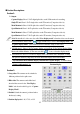
Camera number
Position display
Section Descriptions:
Section 1:
Output:
Capture Display: Show 1-32 Ch digital split video on the VGA monitor for recording.
Single TV out: Show 1-32 Ch single video on the TV monitor (Composite video in).
Main Monitor 0: Show 1-16 Ch split-video on the TV monitor (Composite video in).
Spot Monitor 0: Show 1-16 Ch split-video on the TV monitor (Composite video in)
Main Monitor 1: Show 17-32Ch split-video on the TV monitor (Composite video in).
Spot Monitor 1: Show 17-32 Ch split-video on the TV monitor (Composite video in).
1. Main Monitor 0 & 1 videos are also called “Live display mode” when the videos are shown on
the VGA monitor. Please click “ ” (toggle switch icon) to select “Live display mode” and
“Capture display mode” (each channel will show the time stamp on the video).
2. VGA Monitor 1: Show 1-32 Ch Capture display or 1-16 Ch & 17-32 Ch Live display (Main
Monitor 0 & Main Monitor 1).The user can click“ ” icon to select the display mode.
3. VGA monitor 2: Show 17-32 Ch Live display video, IP Camera video, Playback, or eMap
The spilt TV monitor (composite) can show individual display and rotation when
“Asynchronized Main Monitor display rotation with Capture display” is enabled from
“System configuration” tab.
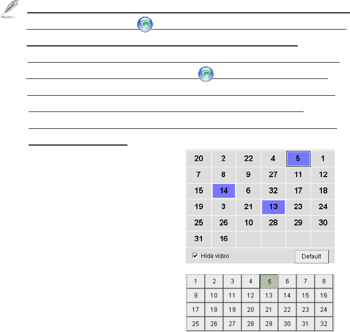
Section 2:
Swap video: The cameras can be switched to
different positions for the spilt screen.
Hide video: The cameras can be hided and
show the blue screen for the “Live Display
Mode” and show the thief logo for “Capture
Display Mode”.
Default: Switch the cameras’ positions back to
the factory’s setting
Position display tab: 1-16, 17-32, or 1-32