Table of Contents About This Guide ------------------------------------------------------------------------------------------------- 4 FCC Compliance Statement ------------------------------------------------------------------------------------ 4 FCC Warning ------------------------------------------------------------------------------------------------------ 4 License Agreement ------------------------------------------------------------------------------------------------ 5 Trademark ---------------------
4-8. Application logs ------------------------------------------------------------------------------ 116 4-9. Peripherals setup ------------------------------------------------------------------------------ 118 4-10. Stop alarm siren ----------------------------------------------------------------------- 122 4-11. Storage configuration ----------------------------------------------------------------- 122 4-12.
About This Guide Conventions used in this guide to make sure that you perform certain tasks properly, take note of the following symbols to use throughout this manual. WARNING: Information to prevent injury to yourself when trying to complete a task. CAUTION: Information to prevent damage to the components when trying to complete a task. IMPORTANT: Information that you must follow to complete a task. NOTE: Tips and additional information to aid in completing a task.
License Agreement Notice to end-user: please read the following legal agreement carefully. Use of the Witness or any of the software provided with this agreement constitutes your acceptance of these terms. If you do not agree with the terms of this agreement, PROMPTLY RETURN the Witness system, Witness, AnyView Pro and FreeView Pro , any related software and the included items (including the Witness video system, written materials and containers) to the location where you purchased them for a full refund.
party rights. If law does not permit such disclaimer of any implied warranty, the duration of any such implied warranties is limited to 90 days from the date of purchase. Some countries do not allow the disclaimer of implied warranties, limitations on how long an implied warranty lasts, or the exclusion or limitation of incidental or consequential damages, so such limitation as or exclusions may not apply to you.
Should you have any questions concerning this Agreement, please contact I-View directly at one of the numbers or addresses listed at the beginning of this manual. Trademark DigiCap II, Deco, e-Witness, @-Witness Pro, u-Witness XP, x-Witness, FreeView Pro, AnyView Pro, PDAVirw and MobileView are registered trademarks of I-View Communication Inc. Microsoft, Windows 95, 98, ME, Windows2000, XP, Vista and 7 are registered trademarks of Microsoft Corporation.
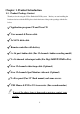
Chapter 1. Product Introduction 1-1. Product Package Content Thank you for choosing the I-View Embedded DVR system.
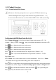
1-2. Product Overview 1-2-1. Front Panel of DVR System The buttons of the front panel provides user to operate the DVR basic functions (e.g. channel switching functions, display modes functions and playback functions … etc.), however, user will need a mouse to connect with the DVR for more detail system setting. Left Section of the DVR Front Panel (Fig 1-3-1.1) Press “Number (0-9)+ “ to view just one camera’s image on the monitor or TV.
Middle Section of the DVR Front Panel (Fig 1-3-1.1 & Fig 1-3-1.2) DVR NO.: Display for the ID address of DVR. The detail setting please refers to Chapter 5-3. HDD: Indicate the status of HDD. Press “On/Off “ key to Turn on / off DVR. Press “ Rec “ key to start recording the video. Press “ 0 “ + “ Rec “ the stop recording. The detail settings please refer to Chapter 6-3. Press “Map” to show the information and map of DVR. Press “ 0 “ + “ Map “ to close the Map screen.
Right Section of the DVR Front Panel (Fig 1-3-1.3) Press key to search for videos in database. Press “ 0 “ + “ “ to close the playback function. Press ► key to play back the video files which you select. Press key once to pause the video file which you select. Press ■ key to stop playback the video file which you select. Press << key to jump to previous frame of the video file, which you select. Press >> key to jump to next frame of videos file which you select.
1-2-2. Back Panel of DVR System According to the different model of the DigiCap DVR, their back panel configuration may be different, please read carefully the introduction below. Digi-9600XP /Digi-9600XP-A Back Panel description: 1. Power plug: Plug power cable. 2. Power switch: Turn on/off power supply. 3. RS-485 Port: The communication port to control the Speed Dome and P/T/Z camera. 4. Series port: Connect to RS-232 device such as Modem.. 5. Printer port: Connect to the printer. 6.
14. Video loop output: The optional 16 (1-16) cameras video loop output. 15. Video loop output: The optional 16 (17-32) cameras video loop output. 16. Video input: The 16 (1-16) video input. 17. Sensor input: 16 sensors input. (For Dry contact input only). 18. Main Monitor 0 output: Display 1-16 spilt video on TV. 19. Main Monitor 1 output: Display 17-32 spilt video on TV. 20.. Relay output: 3 relay output. 21. Audio input: 1-16 audio input. (For Digi-9600XP-A only). 22.
7. USB port: Connect to USB device, such as USB external storage device. 8. LAN port: For TCP/IP connection. 9. Audio plug: Including Microphone in / Speaker out /Line in.. 10. VGA port: The first Monitor VGA port. 11. DVI port: The second monitor connection port. 12. Video loop output: The optional 16 (1-16) cameras video loop output. 13. Video input: The 16 (1-16) video input. 14. Sensor input: 16 sensors input. (For Dry contact input only). 15. Main Monitor 0 output: Display 1-16 spilt video on TV. 16.
4. Series port: Connect to RS-232 device such as Modem. 5. Printer port: Connect to the printer. 6. Panic button port: Connect to push button for emergency call. (Dry contact input only) 7. USB port: Connect to USB device, such as USB external storage device. 8. LAN port: For TCP/IP connection. 9. Audio plug: Including Microphone in / Speaker out /Line in.. 10. VGA port: The first Monitor VGA port. 11. DVI port: The second monitor connection port. 12.
Digi-3248Pro/3248Pro-A Back Panel Description: 1. Power plug: Plug power cable. 2. Power switch: Turn on/off power supply. 3. RS-485 Port: The communication port to control the Speed Dome and P/T/Z camera. 4. Series port: Connect to RS-232 device such as Modem. 5. Printer port: Connect to the printer. 6. Panic button port: Connect to push button for emergency call. (Dry contact input only) 7. USB port: Connect to USB device, such as USB external storage device. 8.
19. Main Monitor 1 output: Display 17-32 spilt video on TV. 20.. Relay output: 3 relay output. 21. Audio input: 1-16 audio input. (For Digi-3248Pro-Aonly) 22. Video out: Display 17-32 single video on TV. 23. Spot Monitor 0 output: The optional 16 (1-16) cameras spot monitor 0 output. 24. Spot Monitor 1 output: The optional 16 (17-32) cameras spot monitor 0 output. The video looping video cannot be used when add the Spot monitor video out. Digi-1648 Pro Back Panel Description: 1.
12. Video loop output: The optional 16 (1-16) cameras video loop 13. Video in: 1-16 cameras video input. 14. Sensor input: 16 sensors input. (For Dry contact input only) 15. Main Spot Monitor 0 output: Display 1-16 split video on TV. 16. Video out: Display 1-16 single video output. 17. Relay output: 3 relay output. 18. Audio input: 1-16 audio input. (For Digi-1648 Pro-A only) 19. Spot Monitor 0 output: The optional 16 (1-16) Spot Monitor 0 output.
1-2-3. DVR Remote Controller Functions 48 keys Remote controller The buttons functions of the remote controller are for user to operate the DVR basic functions (e.g. channel switching functions, display modes functions and playback functions … etc.), however, user will need a mouse to connect with the DVR for detail system setting. Playback single video file If you want to playback the single video clip, press “ S Play “ key and then select the function key of playback.
27 keys Remote controller (Optional) This remote controller special design for the spot monitor application. On your remote controller, there should be buttons labeled with function button and numbers representing the main monitor/spot Monitor and camera numbers. Points the remote controller at the sensor/receiver, press the number of the camera you wish you to on the TV and it would appear. Number key: For the video channels selections.
Press F3 button to control the main monitor 1 and spot Monitor 1 display. Press F4 button to control the Single TV Out (17-32) 2. When you press the Enter, then F2 button that the control will become to “ 4 MUX “ mode. You can control Main monitor 0, Main monitor 1, Spot Monitor 0 and Spot Monitor 1 separately. The control button as below: Press F1 button to control the main monitor 0 display. Press F2 button to control the spot monitor 0 display.
5. The system allows to extent sensor cable for control the TV out from far away site via Remote Controller. Please follow the process as below to achieve this function: a. Please use the shading cable such as 28#2C+S type. b. The sensor cable includes 3-wire cable: Red (DC 5V), Shading cable (Ground), White (Signal). c. Using Standard Cat.
number LED of front panel will be flashed. You can start to use the Remote controller when the LED is flashing. 4. Press “ Return “ key to stop the function of Remote 23 controller.
Chapter 2. Hardware Installation After user finish the CPU, RAM and HDD installation, please remember to go to the system Control Panel to configure the DVR system for installed hardware devices operating properly. For detail about the setup DVR system configuration in control panel, please refer to chapter 3-1 DVR systems Control Panel Configuration. 2-1. Before You Proceed Take note of the following precaution before you install the components (CPU, HDD and RAM). 1.
2-2. Hardware Requirement CPU & RAM request, please refer to the table 2-2.1. 7200RMP hard drive speed or better recommended. Recommend to use the 32M Bytes or better buffer. Please use 7200 RMP HDD when you user 32 channels or Digi4800/9600 XP DVR. Speakers are required for sound alarm/effects. Microphone with 2Vp-p output required for audio recording. Table 2-2.1.
2-3. Central Process Unit (CPU) Installation 2-3-1. CPU Installations: Power Management Setup The DVR’s board comes with a surface mount Socket 775 (LGA775) design for Intel Pentium 4 Processor in the 755-land package. Fig.2-3-1.1 Fig.2-3-1.2 Fig.2-3-1.3 Fig.2-3-1.4 Fig.2-3-1.5 Fig. 2-3-1.6 Follow the steps below for CPU installation 1.) Locate the CPU socket on the platform. (Fig. 2-3.1). 2.
6.) Close the load plate (A), then push the load lever (B) until it snaps into the retention tab. (Fig. 2-3.6) The CPU fits in only correct orientation. 1. Unplug the power cord from the wall socket before touching any component. 2. DO NOT force the CPU into the socket to prevent bending the connectors on the socket and damage the CPU! Fig. 2-3.7 Fig. 2-3.8 2-3-2. The heat sink and fan installation 1.
2-4. Memory Module Installation The Platform comes with Double Data Rate II (DDR II ) socket. These sockets support up to 4 GB system memory. For optimum capability, it is recommended that you obtain memory modules from the same vendor. The following figure shows the location of DDR II sockets and steps to install a RAM. 1. Unlock a socket by pressing the retaining clips outward. 2. Align a DIMM on the socket such that the notch on the DIMM matches the break on the socket. 3.
2-5. HDD Installation The Platform of Digi-1648Pro/3248Pro/3296Pro comes with 1 IDE sockets (1st and 2nd IDE) and 7 (5+2; 2 HDDs for backup) pcs x SATA II sockets. The DigiCap II series DVR support up to 6 pcs x SATA II HDD. The default setting of the manufacture for the 1st IDE socket is used of the DVD+-RW and flash memory. Please follow the steps below to install the Series ATA/SATA II Hard disk. Step 1. Remove the case cover of the DigiCap II Series DVR. Step 2.
Step 4. Mount the connected hard drives into the DigiCap II inner chassis 1 and chassis 2 as showing in Fig 2-6.3 (Allows to install 6 HDD up to 18TB by optional extra RAID interface). Step 5. Screw backs the DigiCap II case cover to complete the HDDs installation. Fig. 2-6.2 Fig 2-6.
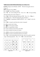
2-6. PTZ Camera Installation Speed dome camera Installation: P/T Motor Installation: The last NC-180AZ PTZ Receiver must be terminated.
Speed dome controlling port description: Pin assignment: RS-485 & Relay out R1: Relay #1 out R2: Relay #2 out Y: Transmitter (TX +) R3: Relay #3 out Z: Transmitter (TX-) A: Receiver (RX+) B: Receiver (RX-) Relays output: Connect one voltage line and ground of Controller (Such as light) to the desired “Relay output” number of Control Board. RS-485: Connect to NC-180AZ PTZ Receiver or Speed dome camera.
1. The “Sensor In” port for Dry contact input only, otherwise it will cause the device damage. 2. The “Relay Out” port for NO (Normal Open) type device only. 3. The current must be less than 10A, when controlling electric device to relay output.
Chapter 3. DVR Operating System DVR System Main Screen Take note of the following precaution before you start to configure the DVR system. 1. The DigiCap II provides Bar-bond system for the distributor, therefore it dose NOT include the HDD and License of Embedded XP. So you must install the HDD first by yourself. Especially you MUST buy the license of Embedded XP from Microsoft, otherwise using the O.S. will be ILLEGALITY. 2. You MUST obey the rules of Microsoft to process the license of Embedded. XP.
3-1. DVR System Control Panel Configuration Once user has finished the CPU, RAM and HDD installation, please click the Control Panel icon ( ) from the right side bottom corner of the DVR system main screen to configure the DVR system.
Control Panel Function Description: File Explore – To select the folder or file. Device Manager – To check the device driver. Ajust Date/Time– To adjust the system time clock. Setup Network Connections– To setup the system network configuration. Display Properties– To setup the system VGA display. Disk Management– To format hard disk when you install a new hard device. Setup Shared Folders– To setup the proper sharing folders for TCP/IP user. DOS Mode – To enable DOS mode.
Auto Dialup- ezDialup– Allow you to auto dial up the 3G modem to connect the Internet when turn on the Witness Pro program. Auto enable program when turn on the DVR. Auto to Dialup 3G Enable Modem Entry the password and user name for auto login Save the setting parameters Entry the phone Connect to the Internet Hang up the modem Set Up Password– Allows you to setup a password to secure the system parameters of the DVR. Set up password to access the control panel.
3-1-1. Adjust Date / Time. Please click icon from Control Panel to set DVR system “Date & Time”, “Time Zone” and “Internet Time”. Fig. 3-1-1.1 Adjust 3-1-2. Setup Network Connections To have DVR remote monitoring and controlling capabilities, user needs to connect DVR with Internet, and set up Network Connections configuration. Please follow the steps below to set up Network configuration. 1. Click icon on the control panel to enter Network Connection configuration display. Fig. 3-1-2.
enter the “Local Area Connection Properties” display. 3. Double click the “Internet Protocol (TCP/IP) “item to enter the “Internet Protocol (TCP/IP) Properties”. Fill out the IP information in each section and press “OK” button twice to complete. Fig. 3-1-2.2 Internet Protocol (TCP/IP) For detail about your network IP address setup, please contact your network supervisor or Local ISP provider for more information.
3-1-3. Display Properties To set up the DVR VGA card display property, simply click the icon on the control panel to enter the “Display properties” interface and press the “Settings” tap on the top for “Screen resolution” and “Color Quality” setting. Fig. 3-1-3.1System Display As Fig. 3-1-3.2 and Fig.3-1-3.3 showing, user can select dual monitor display while connect two monitors with DigiCap II DVR. Fig. 3-1-3.3 Duel monitor display selection Fig. 3-1-3.
3-1-4. Disk Management This chapter walks you through the hard drive formatting in DVR system when you install a brand new hard disk. Please follow the steps below to format the hard disks. 1. Click icon to display the “Disk Management” interface. 2. Click the mouse right button on the new installing HDD, and select “New partition “item. Fig. 3-1-4.1 Select “New Partition” 3. Press “Next” to start the format process. 4. Select “Extended partition “item and click “Next” button to continue. Fig. 3-1-4.
Fig. 3-1-4.3 Select “New Logical Drive” 8. Click “Next” to continue. 9. Select “Logical drive “partition type, and clicks “Next” to continue. Fig. 3-1-4.4 Select “Logical drive” 10. Select “Assign the following drive letter “item, and click “Next” to continue. Fig. 3-1-4.5 Select “Assign the following drive letter”.
11. Select “Format this partition with the following settings “item, and click “Next” to continue. Fig. 3-1-4.6 Select “Format this partition with the following 12. Click “Finish” to complete hard disk partition and format process. 13. Repeat Step 1-12 to format another Hard disk. 3-1-5. Setup Share Folders This chapter will show you how to share the system folder (e.g. ClipPro folder) and to-be-view video files for remote network users. Please follow up the steps below to setup system-sharing folders. 1.
3. While the system displays a “Create A Shared Folder Wizard”, please click “Next” button to continue. Fig. 3-1-5.2 Create a Shared Folder 4. Please click the “Browse” button to select a folder which user wants to share, and fill in the “Share name” section, then press “Next” button and follow the instruction to complete the shared folder sharing. Fig. 3-1-5.3 Browse a share folder 1.
3-1-7. Adjust Volume Control Please click the icon on the system control panel screen to adjust the system volume. Fig. 3-1-6.1 Adjust Volume Control 3-1-7. Saving System Information To make the change effectively after modifying each DVR system configurations, user need to press the “Save System Setting” ( ) icon to complete the changes.
3-2. DVR Main Program 3-2-1.
3-3. Program Overview 3-3-1.