
Manual

32
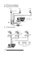
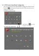
Speed dome controlling port description:
Pin assignment:
RS-485 & Relay out
R1: Relay #1 out R2: Relay #2 out R3: Relay #3 out
Y: Transmitter (TX +) Z: Transmitter (TX-) A: Receiver (RX+) B: Receiver (RX-)
Relays output: Connect one voltage line and ground of Controller (Such as light) to
the desired “Relay output” number of Control Board.
RS-485: Connect to NC-180AZ PTZ Receiver or Speed dome camera.
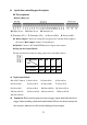
Dip switch of Control Board:
The dip switch for the bound rate setting, please refer to the table as below:
Digital input Module:
G1 – G3: Common 1: Sensor #1 in 2: Sensor #2 in 3: Sensor #3 in
4: Sensor #4 in 5: Sensor #5 in 6: Sensor #6in 7: Sensor #7 in
8: Sensor #8 in 9: Sensor #9 in 10: Sensor #10 in 11: Sensor #11 in
12: Sensor #12 in 13: Sensor #13 in 14: Sensor #14 in 15:Sensor #15 in
16: Sensor #16 in
Sensors in: Each sensor-in port can receive trigger signals from other device to
trigger video recording, alarm and notify function. Please use the dry contact for
the sensor in; otherwise it will cause the damage of sensor input.
Baud rate
Pin
1200
2400
4800
9600
Pin 1 & Pin 2 Short
Open
Short
Open
Pin 3 & Pin 4 Short
Short
Open
Open