
Manual


149
10. Troubleshooting
10.3 Alarm Description Output Using PIO
In PIO patterns 0 to 3 (64 to 512-point positioning type), alarm information can be output using the ports for
completed position output signals (four bits of PM1 to PM8) so that when an alarm occurs, the nature of the
alarm can be identified on the PLC side.
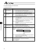
Program the PLC so that whether a given output is a completed position number or alarm can be identified
based on the status of the alarm output signal (*ALM).
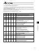
Bit assignment table for alarm description (z= OFF, { = ON)
ALM
PM8 PM4 PM2 PM1 Description: Code number in ( )
{
x x x x Normal
zzz{z
PWRT signal detected during movement (092)
PWRT signal detected before completion of home return
(093)
zzz{{
Deceleration command error (0A7)
zz{zz
Unmatched PCB (0F4)
zz{{z
Parameter data error (0A1)
Position data error (0A2)
Position command information data error (0A3)
Unsupported motor/encoder type (0A8)
zz{{{
Magnetic pole non-confirmation (0B7)
Home sensor not detected (0BA)
Home return timeout (0BE)
Phase Z position error (0B5)
z{zzz
Excessive actual speed (0C0)
z{zz{
Overcurrent (0C8)
Motor power-supply overvoltage (0C9)
Overheating (0CA)
Control power-supply overvoltage (0CC)
Control power-supply voltage low (0CE)
Current-sensor offset adjustment error (0CB)
z{z{{
Deviation overflow (0D8)
Out of push & hold operation range error (0DC)
Software limit over error (0D9)
z{{zz
Unmatched electric angle (0B4)
Overload (0E0)
z{{z{
Encoder phase A/B disconnection detection (0E8)
Absolute encoder error (1) (0ED)
Absolute encoder error (2) (0EE)
Absolute encoder error (3) (0EF)
z{{{z
CPU error (0FA)
z{{{{
Nonvolatile memory write verification error (0F5)
Nonvolatile memory write timeout (0F6)
Damaged nonvolatile memory (0F8)