
Manual


39
4. Operation Using I/O Signals
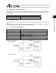
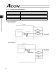
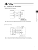
Alarm Signal (*ALM)
This signal turns OFF when the controller’s protective circuit (function) has actuated following an alarm detection
and the basic cutoff procedure has been implemented as a result.
The signal will turn ON if the RES (reset) signal is turned ON after the cause of the alarm has been removed
(except when the alarm relates to a cold-start level error).
When an alarm is detected, a red LED light will illuminate on the front panel of the controller. A green LED remains
on while the controller is operating normally.
Caution: z Identify the cause of each alarm and remove the cause before restarting the controller.
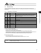
You can check alarm codes using the teaching pendant or PC software. The controller can
store data of up to 16 most recent alarms. This alarm history data will be retained even after
the power is cut off.
Each alarm record is displayed with the time it was generated, so you can check which alarm
occurred when.
z For details on alarm history, refer to 6.3, “Alarms, Causes and Actions.”