
Instruction Manual


7. Operation of MEC Related Controllers
184
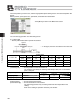
Operation Pattern
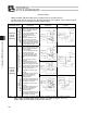
PMEC and AMEC and ERC3 (MEC mode) controllers offer two operation patterns.
The table below gives an overview o the Operationpecification of each pattern. [For the setting methods,
refer to the sections on initial setting and stop position setting.]
Operation pattern
Description
Air cylinder circuit
(Reference)
How to connect motorized
cylinder
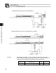
Stopping at
2 points
(2-point
positioning)
Movement by 1 input
between 2 points
[Single-solenoid mode]
You can move the actuator
between 2 points using the same
control you would normally use
with an air cylinder.
You can set the positions of the
end point and start point.
You can specify the moving
speed and
acceleration/deceleration. You
can also specify push-motion
Operation. The actuator moves to
the end point when the ST0 turns
ON, and returns to the start point
when the signal turns OFF.
Movement by 2 input between 2 points
[Double-solenoid mode]
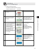
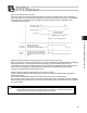
Stopping at
3 points
(3-point
positioning)
Movement by 2 input between
3 points
[3-point positioning]
You can move the actuator
between 2 points using the same
control you would normally use
with an air cylinder.
You can set the positions of the
end point and start point.
You can set the position of an
intermediate point and perform
positioning to the intermediate
point.
You can specify the moving
speed and
acceleration/deceleration. You
can also specify push-motion
operation. The actuator moves to
the end point when the ST1 turns
ON, and moves to the start point
when the ST0 turns ON.
[Intermediate movement mode,
both ON]
When both the ST0 and ST1 are
turned ON, the actuator will
position to and stop at an
intermediate point.
When both the ST0 and ST1 are
turned OFF, the actuator will stop
in the middle of movement.
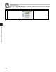
[Intermediate movement mode,
both OFF]
When both the ST0 and ST1 are
turned OFF, the actuator will
position to and stop at an
intermediate point.
When both the ST0 and ST1 are
turned ON, the actuator will stop
in the middle of movement.
(Note) The air cylinder circuits are drawn with symbols of signals corresponding to those used by
PMEC, AMEC and ERC3 (MEC mode) controllers. For details on signals, refer to the
“PMEC, AMEC and ERC3 (MEC mode) operation Manual.”
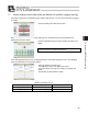
Detection of start position
Detection of end position
Move to end point
Detection of start position
Detection of end position
A
ir cylinde
r
Solenoid A
Sensor
Spring
Motorized cylinder
Dedicated cable
Power
supply
Move to end point
M
o
v
e to e
n
d po
in
t
2
Move to end point 1
Detection of start position
Detection of end position
Motorized cylinder
Power
supply
Dedicated cable
P (Air)
Sensor
Power
supply
Detection of start position
Detection of end position
A
ir cylinde
r
Solenoid A
Solenoid B
Move to end
p
oint 1
Move to start point 2
P (Air)
Sensor
Detection of start position
Detection of end position
A
ir cylinde
r
Solenoid A
Solenoid B
Move to end
p
oint 2
Move to start point 1
Sensor
P (Air)
Detection of start position
Detection of end position
Move si
g
nal 2
Move signal 1
Detection of intermediate point
Detection of start position
Detection of end position
Move si
g
nal 2
Move signal 1
Detection of intermediate point
A
ir cylinde
r
P (Air)
P (Air)
P (Air)
Dedicated cable
Motorized cylinder