
Instruction Manual


Chapter 3 Wiring 3.4 MEC Mode 1 (Operation with PLC)
125
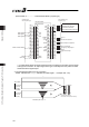
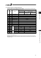
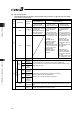
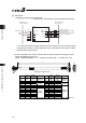
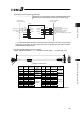
[2] Operation Patterns and Signal Assignments
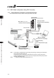
The signal assignment of cable by the operation pattern is as shown below. Follow the table
below to connect external equipment (such as a PLC).
Operation pattern
Stopping at 2 points
(2-point positioning)
Stopping at 3 points
(3-point positioning)
Pin
No.
Wire
Color
Category
Movement by 1 input
between 2 points
[Single-solenoid mode]
Movement by 2 input
between 2 points
[Double-solenoid mode]
Movement by 2 input
between 3 points
[3-point positioning]
A1 Drain Frame ground
FG
B1 BR Control power unit +24V
CP
A2 –
– –
B2 RD
Control power unit 0V CP_GND
A3 RD 1
Brake forcible release BK
B3 OR Motor power unit +24V
MP
A4 OR 1 Emergency-stop input
EMG
B4 YW Motor power unit 0V
MP_GND
A5 –
– –
B5 GN
– –
A6 –
– –
B6 BR 1
– –
A7 BL
– –
B7 PL
– –
A8 GY
– –
B8 WT
– –
A9 BR 2
IN0 ST0 ST0
B9 RD 2
IN1 – ST1
A10 OR 2
IN2 RES RES
B10 YW 2
IN3 – –
A11 GN 2
IN4 – –
B11 BL 2
Input
IN5 – –
A12 PL 2
OUT0 LS0/PE0 LS0/PE0
B12 GY 2
OUT1 LS1/PE1 LS1/PE1
A13 WT 2
OUT2 HEND LS2/PE2
B13 BK
Output
OUT3 *ALM *ALM
Signal with “*” expresses the signal of active low.
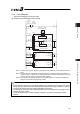
(Reference) Signal of Active Low
Signal with “*” expresses the signal of active low. A signal of active low is a signal that the input signal is
processed when it is turned OFF, output signal is ordinary ON while the power is ON, and turns OFF when
the signal is output.