
Instruction Manual


Chapter 3 Wiring3.5 MEC Mode 2 (Operation Using PIO Converter)
132
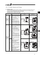
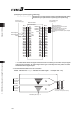
[2] Operation Patterns and Signal Assignments
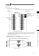
The signal assignment of cable by the operation pattern is as shown below. Follow the
following table to connect the external equipment (such as PLC).
Operation pattern
Stopping at 2 points
(2-point positioning)
Stopping at 3 points
(3-point positioning)
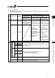
Pin
No.
Wire
Color
Category
Movement by 1 input
between 2 points
[Single-solenoid mode]
Movement by 2 input
between 2 points
[Double-solenoid mode]
Movement by 2 input
between 3 points
[3-point positioning]
1A BR-1 – –
2A RD-1 – –
3A OR-1 – –
4A YW-1 – –
5A GN-1 IN0 ST0 ST0
6A BL-1 IN1 – ST1
7A PL-1 IN2 RES RES
8A GY-1 IN3 – –
9A WT-1 IN4 – –
10A BK-1 IN5 – –
11A BR-2 IN6 – –
12A RD-2 IN7 – –
13A OR-2 IN8 – –
14A YW-2 IN9 – –
15A GN-2 IN10 – –
16A BL-2 IN11 – –
17A PL-2 IN12 – –
18A GY-2 IN13 – –
19A WT-2 IN14 – –
20A BK-2
Input
IN15 – –
1B BR-3 OUT0
LS0/PE0 LS0/PE0
2B RD-3 OUT1
LS1/PE1 LS1/PE1
3B OR-3 OUT2
HEND LS2/PE2
4B YW-3 OUT3
*ALM *ALM
5B GN-3 OUT4 –
6B BL-3 OUT5 –
7B PL-3 OUT6 –
8B GY-3 OUT7 –
9B WT-3 OUT8 –
10B BK-3 OUT9 –
11B BR-4 OUT10 –
12B RD-4 OUT11 –
13B OR-4 OUT12 –
14B YW-4 OUT13 –
15B GN-4 OUT14 –
16B BL-4
Output
OUT15 –
17B PL-4 –
18B GY-4 –
19B WT-4 –
20B BK-4 –
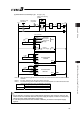
Signal with “*” expresses the signal of active low.
(Reference) Signal of Active Low
Signal with “*” expresses the signal of active low. A signal of active low is a signal that the input signal is
processed when it is turned OFF, output signal is ordinary ON while the power is ON, and turns OFF when
the signal is output.