
Instruction Manual


Chapter 4 Operation 4.2 Operation in Positioner Mode
4.2.3 Operation in Positioner Mode 2 (Operation Using PIO Converter)
207
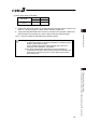
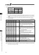
{: ON z: OFF
*ALM
ALM8
(PM8)
ALM4
(PM4)
ALM2
(PM2)
ALM1
(PM1)
Binary Code
Description: Alarm code is shown in ( ).
z { z z z
8 Actual speed excessive (0C0)
z { z z {
9
Overcurrent (0C8)
Overvoltage (0C9)
Overheat (0CA)
Control power source voltage error (0CC)
Drop in control supply voltage (0CE)
Drive source error (0D4)
z { z { {
11
Command counter overflow (0A4)
Command counter overflow in Incomplete home
return (0D5)
Deviation Overflow (0D8)
Software stroke limit over error (0D9)
Pressing motion range over error (0DC)
z { { z z
12
Servo error (0C1)
Overload (0E0)
z { { z {
13
Encoder receipt error (0E5)
Absolute encoder error detection 1 (0ED)
Absolute encoder error detection 2 (0EE)
Absolute encoder error detection 3 (0EF)
z { { { z
14
CPU Error (0FA)
Logic Error (0FC)
z { { { {
15
Nonvolatile memory write verify error (0F5)
Nonvolatile memory write timeout (0F6)
Nonvolatile memory data destroyed (0F8)
(Note) *ALM Signal is an active low signal. It is ON when the power is applied to the controller, and
turns OFF when the signal is output.