
Instruction Manual


Chapter 4 Operation4.3 Operation in Pulse Train Control Mode (How to Operate
Pulse Train Control Type)
256
(2) Format Settings of Command Pulse Train
Set the command pulse train format in Parameter No.63 and active high/low in No.64.
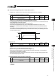
I. Command Pulse Mode
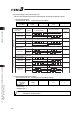
User Parameter No.63 “Command Pulse Input Mode”
Name Symbol Unit Input Range Initial Value
Command Pulse
Input Mode
CPMD – 0 to 2 1
PP
•
/PP
NP
•
/NP
PP
•
/PP
NP
•
/NP
PP
•
/PP
NP
•
/NP
PP
•
/PP
NP
•
/NP
PP
•
/PP
NP
•
/NP
PP
•
/PP
NP
•
/NP
High Low
HighLow
Normal Rotation
Pulse Train
Normal Rotation
Pulse Train
Reverse Rotation
Pulse Train
Reverse Rotation
Pulse Train
The normal rotation pulse train shows the motor rotation amount in normal direction, and
reverse rotation pulse train shows the motor rotation amount in reverse direction.
Pulse Train
Pulse Train
Symbol
Symbol
The command pulse shows the motor rotation amount and the command symbol shows the
rotation direction.
A/B Phase
Pulse Train
A/B Phase
Pulse Train
The A/B Phase 4-fold Pulse with the phase difference of 90° shows the commands for
the rotation amount and direction.
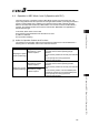
Command Pulse
Train Mode
Input
Terminal
In Normal Rotation
In Reverse Rotation
Negative LogicPositive Logic
Setting Value
of Parameter
No. 63
2
1
0
2
1
0
II. Command Pulse Mode Input Polarity
User Parameter No.64 “Command Pulse Input Mode Polarity”
Name Symbol Unit Input Range Initial Value
Command Pulse
Input Mode
Polarity
CPMD – 0 to 1 0
Set Value
Positive logic : 0
Negative logic : 1
Caution: Pay attention not to exceed the specification limit when setting the velocity,
acceleration and deceleration.