
Instruction Manual


Chapter 6 Adjustment of Operation6.3 I/O Parameter
6.3.1 Positioner Mode 1, Positioner Mode 2 and Pulse Train Control Mode
308
[2] Detail Explanation of Parameters
Caution: To make the setting enable after a change is made to parameters, have either
the software reset or power reboot.
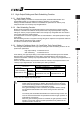
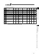
(1) Zone 1+, Zone 1- (Parameter No.1, No.2)
Zone 2+, Zone 2- (Parameter No.23, No.24)
No. Name Symbol Unit Input Range Default factory setting
1 Zone 1+ ZNM1 mm
-9999.99 to
9999.99
Actual stroke on +
side
2 Zone 1- ZNL1 mm
-9999.99 to
9999.99
Actual stroke on - side
23 Zone 2+ ZNM2 mm
-9999.99 to
9999.99
Actual stroke on +
side
24 Zone 2- ZNL2 mm
-9999.99 to
9999.99
Actual stroke on - side
Enable zone signal outputs are to be determined by Parameter No.25 “PIO Pattern Select” and
Parameter No.149 “Zone Output Switchover”.
[Refer to the Parameter No.149 for the details]
The minimum setting unit is 0.01mm.
If a specific value is set to both zone setting + and zone setting -, the zone signal is not output.
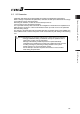
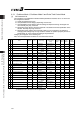
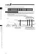
A setting sample is shown below.
[Example of linear axis]
Caution: The signal cannot be output unless the range of the zone detection is set to a
value greater than that of the minimum resolution (actuator lead length/800).
0mm 30mm 70mm
ON
ON ON
100mm
Current Position
Zone signal output
Zone signal output
Set Value
Zone setting + : 70mm
Zone setting - : 30mm
Set Value
Zone setting + : 30mm
Zone setting - : 70mm