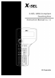
X-SEL ANSI-Compliant Teaching Box Instruction Manual Ver. 1.
1. Introduction ........................................................................................................ 1 2. Before Use ......................................................................................................... 1 3. Safety Precautions ............................................................................................. 2 4. Warranty Term and Coverage ............................................................................ 3 5. Connection to Controller ...
13. Symbol Editing ................................................................................................. 94 13-1. 13-2. 13-3. 13-4. Symbol editing items ............................................................................................95 Input example: Symbolization of local integer variables .......................................96 Symbol edit screen for each item .......................................................................100 Flash ROM writing ...........................
1. Introduction Thank you very much for purchasing our Teaching Box for the X-SEL Controller. Improper usage or mishandling may result in a product not only being unable to deliver full functions but also produce unexpected troubles or shorten the product’s life. Please read this Manual carefully, and operate the product properly by paying attention to its handling. When operating the Teaching Box, always keep this Manual on hand and read the relevant items as required.
3. Safety Precautions (1) Use a genuine product specified by us for wiring between the actuator and X-SEL Controller. (2) Keep out of the operating range of a machine such as an actuator while it is operating or in a ready state (condition in which the controller’s power is ON). When using it in places where persons may approach, fence it off. (3) Before carrying out assembly and adjustment work or maintenance and inspection work of the machine, be sure to disconnect the power cord.
4. Warranty Term and Coverage The Teaching Box you purchased has been delivered upon completion of our strict shipping test. We shall warrantee this product as follows: 1. Warranty term The warranty term shall be either of the following terms, whichever is reached first. ƒ 18 months after our shipment ƒ 12 months after delivery to the place designated by you 2.
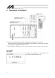
5. Connection to Controller MODE switch 㽲 Connect the controller to the actuator, IO 24V power, system IO, etc., in advance. Connect the cable connector of the Teaching Box to the controller’s teaching connector when the main power supply of the controller is OFF. 㽳 After flipping the MODE switch of the controller to MANU, turn on the power to the controller. Teaching Box LCD display It displays the version of the Teaching Box and moves to the Mode Selection screen.
When the Deadman switch is OFF, the screen shown at the left is displayed. Pressing the ESC key moves to the Mode Selection screen. (Even when the Deadman switch is OFF, operations in the mode not requiring servo ON are available.) When the MODE switch is flipped to AUTO, connection to the controller is not established and the screen shown at the left is displayed. In this case, press the ESC key to move to the reconnection (Cnct) screen.
! CAUTIONS When “OPEN 1” (channel 1 shared for the Teaching Box) is executed within the SEL program in the MANU mode, the right of use of the serial port channel 1 is forcefully moved to the SEL program and communication with the Teaching Box is disconnected. The program is running. (*Error No. A5D “SCIF open error in non-AUTO mode”) To stop operation after that, be sure to press the EMERGENCY STOP button. (Be careful especially under jog operation.
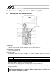
6. Functions and Specifications of Teaching Box 6-1. Main operation keys and their functions 㽲 LCD display It displays the program or operation monitor up to 8 lines of 32 characters. 㽳 EMERGENCY STOP button It makes an emergency stop. 㽴 Deadman switch The Deadman switch has 3-level conditions.
㽵 F1 F2 F3 and F4 keys (function keys) These keys correspond to each item in the LCD display (function key section). 㽶 SF key (shift key) When there are 5 or more selectable functions (㸢 is displayed at the right part of the function key section), the display items in the function key section are shifted. 㽷 ESC key (escape key) It returns the current condition to the previous condition. When this key is used during data input, the input data is canceled.
㽽 Status display LED Conditions when each LED is lit are as follows: JOG SERVO MOVE HOME SVOFF S-VEL ERROR EMG POWER READY Condition when LED is lit Jog operation is available with the 1- to ALL- or 1+ to ALL+ keys. The servo ON/OFF commands are available with the 1- to ALL- or 1+ to ALL+ keys. Position movement and continuous movement are available with the 1- to ALL- or 1+ to ALL+ keys. Home position return operation is available with the 1- to ALL- or 1+ to ALL+ keys.
㾃 Axis operation keys (1- to ALL-, 1+ to ALL+) These keys operate each axis. The functions are as follows according to the operation mode: Operation mode JOG POSITION MOVEMENT Function 1- to 4-, ALLIt jogs (inches) the axis in the coordinate minus direction. It moves the axis to the currently displayed position. (In the continuous movement mode, it decrements the position No. after completion of movement.) It gives the servo OFF command.
7. Mode Flow Chart Power ON Communications established Function key Mode selection Function key (Edit) Function key (Position) Select position No. and press return (Manual input) Position data input * After writing data with [WRT], move to the next position * When escaping the mode with [ESC], check whether to write in FROM. Select position No.
Select the Select the program No. step No. and and press return press return Function key (Program) (Change) Step data input * After writing data with [WRT], move to the next step * Move to the symbol edit mode with [Sym] (Copy/movement) (Clear) Select the symbol type with the function key Symbol/ definition value input (Symbol) * After writing data with [WRT], move to the next edit No.
Function key (Monitor) (Input port) (Output port) (Global flag) Function key (Global variable) (Integer variable) (Real variable) (String variable) Function key (Axis status) (Current position) (Servo status) (Sensor input status) (Encoder status) (Axis-related error) 13
Function key (System status) (System mode) (System error) (System status 1) (System status 2) (System status 3) (System status 4) (Error list) Function key (Version) (CTL main) (Driver) (Teaching pendant) 14
Function key (Controller) (FROM wring) (Software reset) (Error reset) (Memory initialization) (Reconnection) (Baud rate change) (Driving power recovery request) (Action restart request) (Absolute reset) Velocity effect select * When the manual operation type parameter equals edit and start selection (with password), it is required to enter the password at setting change time.
8. Data Storage Method Since the X-SEL Controller adopts flash memory, there is a storage area by battery backup and a storage area by flash memory according to the data to be stored. In addition, even if data is transferred from the PC software or Teaching Box, the data is only to be written in memory as shown in the chart below and the data is erased by power-off or controller reset. To ensure data storage, write the data you want to store in flash memory. 8-1.
Since the program, parameter, and symbol are read from flash memory at restart time, the data in memory becomes the original data before editing unless the data is written in flash memory. The controller always operates according to the data in memory (within the dotted box) excluding parameters. Content 1: Parameters excluding content 2 below and encoder parameters Content 2: Driver card and IO slot card (power-supply system card) parameters Content 3: Flags, variables, strings 8-2.
8-3. Cautions Cautions in data transfer and flash writing Never turn off the main power during data transfer and flash writing. Failure to do so may result in inoperability of the controller due to data loss. Cautions in storing parameters in a file Encoder parameters are stored in EEPROM of the actuator’s encoder itself (not in EEPROM within the controller, which is different from the other parameter types).
9. Simple Operating Procedures In this section, the program and position data to draw a simple “pentagon” passing through the following 6 points (㽲 and 㽷 at the same location) by the actuator of 2 axes (X, Y) are created.
9-1. Creation of position data Input the position data of 6 points each to draw a pentagon as shown in the position data list below. Enter numeric values of the position data with the ten-key numeric pad. Connect the controller to the Teaching Box and flip the MODE switch to MANU. Turn on the power to the controller. The version of the Teaching Box is displayed and the screen moves to the Mode Selection screen.
Mode Selection screen This screen becomes the basic screen for all operations. Press the F1 (Edit) key. * When you make a selection error or input error, press the ESC key to return to the last screen and continue operation. Pressing the ESC key once or several times during an operation can return to the basic screen shown above without fail. Edit mode screen Press the F1 (Posi) key. Posi (position data) edit screen Press the F1 (Mdi) key. 1st axis data 3rd axis data 2nd axis data Position No.
㽲 Data input for 1st point Enter a numeric value of 0 and press the return key. 0.000 is displayed, the axis No. changes to 2, and the cursor moves to the section for the 2nd-axis position data. * The position data can be input up to a 4-digit integral number and three digits to the right of the decimal. Since the range varies according to the actuator’s model, check it in the catalog etc. Enter 50 for the 2nd-axis position data and press the return key.
The cursor moves to the section for the 2nd-axis position data. Enter 100 and press the return key. Transfer the data with the WRT key and advance the position No. to 3. 㽴 Data input for 3rd point Enter 100 for the 1st-axis position data and press the return key. Enter 50 for the 2nd-axis position data and press the return key.
Transfer the data with the WRT key and advance the position No. to 4. 㽵 Data input for 4th point Enter 100 for the 1st-axis position data and press the return key. Enter 0 for the 2nd-axis position data and press the return key. Transfer the data with the WRT key and advance the position No. to 5.
㽶 Data input for 5th point Enter 0 for the 1st-axis position data and press the return key. Enter 0 for the 2nd-axis position data and press the return key. Transfer the data with the WRT key and advance the position No. to 6. 㽷 Data input for 6th point Enter 0 for the 1st-axis position data and press the return key.
Enter 50 for the 2nd-axis position data and press the return key. Transfer the data with the WRT key and advance the position No. to 7. Complete position editing and write the data in flash ROM. Pressing the ESC key moves the cursor to the location of the position No. Pressing the ESC key returns the screen to the Posi edit screen.
Pressing the ESC key again moves to the Edit mode screen. Pressing the ESC key once more moves to the Flsh (flash ROM writing) screen. When writing the data in flash ROM, press the F1 (OK) key. When exiting the Edit mode without writing the data, press the F2 (Canc) key. Pressing the ESC key returns to the last screen. However, if you attempt to exit the Edit mode, the screen returns to the Flsh screen again. The message “Please wait…” flashes during flash ROM writing.
When flash ROM writing is completed, the screen returns to the Edit screen. With the above, input of the basic position data is completed.
9-2. Creation of program The program to move the position data created in 9-1. is created. Application Program List In this section, the X-SEL program is inputted. For further information on the meaning and usage of each command, refer to the Instruction Manual attached to the controller. Only Cmnd (command) and Operand1 (operation 1) are input here. Cautions for the HOME command For restart after home position return temporary stop, execute it from the beginning of the home position return sequence.
Select the F1 (Edit) key on the Mode Selection screen. Select the F2 (Prog) key on the Edit mode screen. Number of all program steps stored in the controller’s RAM Select the F1 (Mdfy) key on the Prog (program edit and new creation) screen. Program No. Step No. Number of program steps stored in the controller’s RAM for the selected program No. 30 The screen changes to the Mdfy (program No. input mode) screen. The cursor is located at the program No.
The cursor has moved to the location of the step No. Press the return key. The cursor moves to the input section for Ext (extension condition). Move the cursor to the input section for Cmnd (command) with the return key or Ż ź Ÿ Ź keys.
Enter a command. The command is displayed in the function key section. Command search method 㽲 When the cursor is at the location for command input, pressing the SF key displays commands in alphabetical order. Command with an initial letter of G Command with an initial letter of H Command with an initial letter of I 32 㽳 Letters/alphabet letters are located for each of the ten keys (such as GHI allocated to the 9 key).
After displaying HOME in the function key section, press the F3 (HOME) key. (To return the command input field to blank, press the BS key.) Press the return key. The cursor moves to Op-1. Enter 11 and press the return key. To reattempt input: Move the cursor to the change location with the ĸ or return key. Overwrite the data or delete it with the BS key. Or, reattempt from the step No. with the ESC key. Press the WRT key to transfer the data to the controller. The step No. advances to 2.
Select the F3 (VEL) key. Press the return key. Enter 100 for the velocity* here and press the return key. * For the maximum velocity, check it with the catalog etc. When the velocity is input for the position data, that velocity is given priority. Press the WRT key to transfer the data to the controller. The step No. advances to 3. * When the screen is changed with the PAGE UP and PAGE DOWN keys or ESC key before data transfer, the input data becomes invalid.
Display MOVL with 5 of the ten-key numeric pad and the SF key. Select the F2 (MOVL) key. Press the return key. The cursor moves to the section for Op-1. Enter 1 of the position No. 1 and press the return key.
Press the WRT key to transfer the data to the controller. The step No. advances to 4. * When the screen is changed with the PAGE UP and PAGE DOWN keys or ESC key before data transfer, the input data becomes invalid. Input the program data of MOVL 2 to MOVL 6 for the steps No. 4 to No. 8 according to the same procedures and transfer the data to the controller. Display EXIT in the function key section with 8 of the ten-key numeric pad and the SF key. Select the F4 (EXIT) key and press the return key.
Press the WRT key to transfer the data to the controller. * When the screen is changed with the PAGE UP and PAGE DOWN keys or ESC key before data transfer, the input data becomes invalid. Complete the program editing and write the data in flash ROM. Press the ESC key. (The cursor moves to the location for step No.) (The cursor moves to the location for program No.) Press the ESC key. Return to the Prog screen.
Press the ESC key. Return to the Edit screen. Press the ESC key. When writing the data in flash ROM, press the F1 (OK) key. When not writing the data in flash ROM, press the F2 (Canc) key. The message “Please wait…” flashes during flash ROM writing. * Never turn off the power to the controller during this time.
When flash ROM writing is completed, the screen returns to the Edit screen.
9-3. Change of application program The program created in the preceding section (9-2) is changed. A program step is inserted or deleted to allow the same operation to be repeated. Step No. Change (Insert “TAG 1” into step No. 3, delete “MOVL 6” and overwrite “EXIT” with “GOTO 1”) Select the F1 (Edit) key on the Mode Selection screen. Press the F2 (Prog) key on the Edit screen.
Select the F1 (Mdfy) key on the Prog screen. The display changes to the Mdfy screen. Press the return key once to move the cursor to the location for step No. Insert one-line step between the program steps No. 2 and No. 3. Enter 3 with the ten-key numeric pad or press the PAGE UP key twice to display 3. Select the F1 (Ins) key. “Ins” is displayed next to Mdfy.
Press the return key to confirm the step No. to insert. Move the cursor to Cmnd (command) input section with the return key or Ż ź Ÿ Ź keys. Display TAG with 1 of the ten-key numeric pad or the SF key. Select the F4 (TAG) key and press the return key.
Enter a numeric value of 1 for Op-1 and press the return key. Press the WRT key to transfer the program data to the controller. * When the screen is changed with the PAGE UP and PAGE DOWN keys or ESC key before data transfer, the input data becomes invalid. Press the ESC key twice to display the screen for step No. 4. Then, delete MOVL 6. Enter 9 for the step No. directly with the ten-key numeric pad while keeping the cursor position, or press the PAGE UP key 5 times to display MOVL 6.
Press the F2 (Del) key. Press the F2 (Del) key again. (When canceling deletion, press the ESC key.) Press the return key. Move the cursor to the Cmnd (command) input section with the return key or Ż ź Ÿ Ź keys.
Display GOTO with 9 of the ten-key numeric pad or the SF key. Select the F2 (GOTO) key and press the return key. Enter the same numeric value as the one input for Op-1 of TAG for Op-1. Enter 1 here and press the return key. Press the WRT key to transfer the program data to the controller. * When the screen is changed with the PAGE UP and PAGE DOWN keys or ESC key before data transfer, the input data becomes invalid.
Press the ESC key several times to move to the Flsh screen. When writing the data in flash ROM, press the F1 (OK) key. When not writing the data in flash ROM, press the F2 (Canc) key. The message “Please wait…” flashes during flash ROM writing. * Never turn off the power to the controller during this time. Flash ROM writing is completed. Return to the Edit screen with the ESC key.
10. Program Execution Now, operate the program created in “9. Simple Operating Procedures.” 10-1. Operation check Press the F2 (Play) key to move to the Play mode screen. Play mode screen All programs completed The following 3 items on the Play mode screen exist. F1 (Run): Moves to the screen for inputting the program No. to execute. F2 (TSts): Moves to screen for monitoring the status of the task in execution. F3 (Stop): Completes all programs in execution.
The screen has moved to the Run mode selection screen. Select whether to make a run by 1 step of the program or to make a continuous run. Run mode selection Start a continuous run with the F1 (Cont) key. Run [Cont] mode The program step currently in execution is displayed (excluding the continuous movement system command). Pressing the F2 (Sus) key changes to a step run. Pressing the F3 (Stop) key completes running.
10-2. Setting of break point The break points in a continuous run can be set. Press the F4 (Brk) key on the Run mode selection screen or Run mode screen. Step No. 10-3. Setting of break point Select the step No. to set the break point with the PAGE UP and PAGE DOWN keys. Every time the F1 (Set) key is pressed, the break point is set or cleared. When clearing all the set break points, press the F2 (AClr) key.
(2) Local flags The ON/OFF conditions of local flags are displayed. The conditions of local flags can be changed between ON and OFF. Select the F2 (LFlg) key on the Run mode screen. Mode flow: Program No. Every time the F1 (0/1) key is pressed, the local flag can be changed between ON and OFF. Move the cursor with the Ż ź Ÿ Ź keys. Every time the PAGE UP or PAGE DOWN key is pressed, the flag Nos. are shifted by 20 and displayed.
㽴 Local string Mode flow: The cursor is located at the data (column). Entering an ASCII code with the ten-key numeric pad and pressing the return key can assign characters. (A to F of hexadecimal notation can be input by changing Num to Alph with the F1 [Alph/Num] key.) Move the cursor with the return key or Ż ź Ÿ Ź keys. The PAGE UP and PAGE DOWN keys display the column Nos. by shifting the numbers by 50. The ACII codes excluding 20h to 7Eh are displayed as “ƒ”.
11. Position Editing 11-1. Mdi (numeric input) Method of inputting a numeric value with the ten-key numeric pad for position data For the data input of the coordinate position with the ten-key numeric pad, refer to “9. Simple Operating Procedures.” Method of inputting Vel (velocity), Acc (acceleration), and Dcl (deceleration) for each position No. Example of Mdi (numeric input): Mode flow to numeric input screen: Position No. + return Move the coordinate value, Vel, Acc, or Dcl section with the Ÿ ź keys.
11-2. Teac (teaching) Teaching (method in which an actuator is moved to any given position and the current positions of the actuator are incorporated as data) is the method for inputting position data. As the methods of moving the actuator to any given position, jog operation, inching operation, and manual operation in a servo OFF condition exist. The basic flow of teaching is as follows: 㽲 Move the actuator.
(1) Teac screen As the Teac screen, the position No. selection screen and the axis-specific data input screen exist. On the position No. selection screen, teaching (current-position incorporation/clear) is given to all axes simultaneously. On the axis-specific data input screen, teaching is given on an axis basis. 㽲 Position No. selection screen Function key descriptions F1 (Clr): Pressing it twice clears the all-axis data of the position No. selected.
㽴 Servo ON/OFF The axial servo ON/OFF is executed on an axis basis or for all axes simultaneously on the Teac screen. Press the SERVO key to light up the SERVO status display LED. Servo ON/OFF procedures For Servo ON For Servo OFF Press the plus (+) axis operation key with the axis No. for servo ON. (When turning the servo ON for the Axis No. 1, press the 1+ key.) When turning off the servo, press the minus (-) axis operation key with the axis No.
㽵 Home position return For the increment specification, it is required to execute home position return before teaching after turning on the power. Home position return is executed on an axis basis or for all axes at a time on the Teac screen. Turn on the servo for the axis to be returned to the Home position return home, in a Teac screen condition. (It is not required if procedures the axis is already in a servo ON condition.) Press the HOME key to light up the HOME status display LED.
(2) Movement of actuator 㽲 Jog operation Jog operating procedures Turn on the servo for the axis to be jogged, in a Teac screen condition. (It is not required if the axis is already in a servo ON condition.) When any status display LED of SERVO, MOVE, and HOME is lit (JOG is extinguished), press the ESC key to light up the JOG status display LED. Press the axis operation key (1+ 1- 2+ 2- 3+ 3- 4+ 4-) with the axis No. for movement to move the actuator to any given position.
㽳 Inching operation Inching distance: 0.1 mm Set the inching distance (travel made every time the JOG key is pressed once). Enter a numeric value for Dis (inching distance) with the ten-key numeric pad on the JVel screen. The numeric input range is between 0.001 and 1.000 (unit: mm). Return to the Teac screen with the ESC key to execute inching operation. Clicking the axis operation key once makes 1-inching distance movement.
(3) Incorporation of current positions as data The confirmed positions of the actuator are incorporated as position data onto the Teac screen. Enter the position No. into which data is incorporated with the ten-key numeric pad on the position No. selection screen, and press the return key. Or, select the position No. into which data is incorporated with the PAGE UP and PAGE DOWN keys on the data input screen. On the position No.
(5) I/O monitoring and position check Input and output ports can be monitored during teaching operation. In addition, it is also possible to move the actuator to the location of the position data with teaching and check its position. 㽲 I/O monitoring Select In or Out among the function keys in a Teac screen condition. In: Input ports Out: Output ports The port No. display can be changed with the PAGE UP and PAGE DOWN keys.
㽳 Movement The actuator is moved to the location of the position data transferred to the controller. Movement procedures Position No. + return Select the position No. you want to move in a Teac screen condition and press the return key. Turn on the servo for the axis to be moved. (It is not required if the axis is already in a servo ON condition.) Press the MOVE key to light up the MOVE status display LED. Pressing the axis operation key with the axis No. for movement begins axis movement.
When checking or changing the movement velocity, press the F3 (JVel) key to move to the screen for changing the velocity etc. Movement velocity: 50 mm/sec. 62 Enter the change data with the ten-key numeric pad and press the return key. After changing, return to the previous screen with the ESC key.
㽴 Continuous movement The actuator is continuously moved to the location of the position data transferred to the controller. Select the position No. to which you want to move Continuous movement the actuator first in a Teac screen condition, and procedures press the return key. First position No. Turn on the servo for the axis to be continuously Return moved. (It is not required if the axis is already in a servo ON condition.) Press the F4 (Cont) key among the function keys. (Refer to the following page.
When checking and changing the movement velocity, press the F3 (Jvel) key to move to the screen for changing the velocity etc. Movement velocity: 50 mm/sec. Enter the change data with the ten-key numeric pad and press the return key. After changing, return to the previous screen with the ESC key. (In the figure at the left, the movement velocity is set to 50 mm/sec.) Note: Please take note that it may take a few seconds before movement start after the JOG key is pressed.
(6) User-specified output port operation The output ports set for the parameter can be easily turned ON/OFF. Select UsrO among the function keys in a Teac screen condition. (A) User-specified output port status The conditions of user-specified output ports are displayed as 1 (=ON) and 0 (=OFF). (The conditions are displayed from the first specified port for the number of the specified ports.
㽲 Setting of user-specified output port parameters For the operation method for parameter setting, refer to “14. Parameter Editing.” The first port No. and the number of ports are set with the following parameters: ƒ Number of ports I/O parameter No. 74 “Qnt Prt Usr Out” (Number of output ports used by TP user [hand etc.]) ƒ First port No. I/O parameter No. 75 “Top No. Use Out” (First output port No. by TP user [hand etc.]) (Setting example) When the first port No.
11-3. Teaching input example Data is input for the position No. 10 by jog operation and for the position No. 11 by manual operation under servo OFF. Select the F1 (Edit) key on the Mode Selection screen. Select the F1 (Posi) key. Select the F2 (Teac) key. Enter 10 for the position No. with the PAGE UP and PAGE DOWN keys or the ten-key numeric pad and confirm it with the return key.
Turn on the servo for all axes and execute jog operation. Jog operating procedures Press the SERVO key to light up the SERVO status display LED. Press the ALL+ key. (Servo ON for all axes) (When the Deadman switch is OFF, the servo is not turned ON.) The JOG status display LED lights up. Press the axis operation key with the axis No. to be moved (1+ 1- 2+ 2-) to move the actuator to any given position. (1 and 2 indicate the axis No.
Press the return key to move the cursor to the next axis, and press the F2 (Scan) key. Press the WRT key to transfer the position data to the controller. The position No. advances to 11. * When the screen is changed with the PAGE UP and PAGE DOWN keys or ESC key before data transfer, the input data becomes invalid. Press the EMERGENCY STOP button to turn off the servo. (Or, turn off the Deadman switch.) Check that the EMG status display LED is lit.
Press the ESC key to return to the Teac screen. To move the Z-axis manually, it is required to release the brake. Therefore, the Z-axis may lower by the weight of the hand attached to the end when the brake is released. Do not carry out teaching for manual movement to the Z-axis. Move each axis to any given position manually. Pressing the F2 (Scan) key incorporates the current position of the axis No. over which the cursor is located onto the input screen.
Complete the position data input by teaching. Press the ESC key. Press the ESC key. Press the ESC key. Press the ESC key.
When writing the data in flash ROM, press the F1 (OK) key. When not writing the data in flash ROM, press the F2 (Canc) key. The message “Please wait…” flashes during flash ROM writing. * Never turn off the power to the Controller during this time. When flash ROM writing is completed, the screen returns to the Edit screen.
11-4. Copy and movement of position data The following operating instructions are to copy or move the position data to another position No.: Select the F1 (Edit) key on the Mode Selection screen. Select the F1 (Posi) key. Select the F3 (Copy) key. Positions from which data is copied or moved First No. Last No. Enter the first No. of the positions from which data is copied or moved with the ten-key numeric pad and press the return key. Enter the first No.
When executing copy or movement, press the F1 (OK) key. When canceling it, press the ESC key. The display returns to the previous screen. When writing the data in flash ROM, press the ESC key several times to return to the Flsh screen. Press the F1 (OK) key to execute flash ROM writing.
11-5. Deletion of position data The following operating instructions are to delete the position data: Select the F1 (Edit) key on the Mode Selection screen. Select the F1 (Posi) key. Select the F4 (Clr) key. Position data to delete First No. Last No. Enter the first No. and the last No. of the position data to delete with the ten-key numeric pad and press the return key. When deleting the selected position data, press the F1 (Clr) key. When deleting the data for all positions (No. 1 through No.
When executing deletion, press the F1 (OK) key. When canceling it, press the ESC key. The display returns to the previous screen. When writing the data in flash ROM, press the ESC key several times to return to the Flsh screen. Press the F1 (OK) key to execute flash ROM writing.
12. Program Editing 12-1. Program input method The following program is input with the Teaching Box (for explanation of input procedures): The program step No. 1 is used to input the extension condition only, No. 2 is used to input all but comment, and No. 3 is used to input a character string.
Select the F1 (Edit) key on the Mode Selection screen. Select the F2 (Prog) key on the Edit screen. Select the F1 (Mdfy) key on the Prog screen. Enter the program No. with the ten-key numeric pad and press the return key.
The cursor has moved to the location of the step No. Press the return key. Input section for Ext Press the return key. Input section for N and Cond Enter 601 with the ten-key numeric pad and press the return key. Press the WRT key to transfer the data of step No. 1 to the controller. The step No. advances to 2. * When the screen is changed with the PAGE UP and PAGE DOWN keys or ESC key before data transfer, the input data becomes invalid.
Move the cursor to the input section for Ext with the return key or Ÿ ź keys. Input section for Ext Select the F2 (A) key and press the return key. Even for the extension condition of the pseudo ladder task, input it by the function key on this display screen. Input section for N and Cond Select the F3 (N) key first. Enter 600 with the ten-key numeric pad and press the return key. Input section for Cmnd Display CPGE in the function key section with 7 of the ten-key numeric pad and the SF key.
Select the F2 (CPGE) key and press the return key. Input section for Op-1 Enter 200 with the ten-key numeric pad and press the return key. When specifying a variable to Operand 1 indirectly, select the F3 (*) key first. Input section for Op-2 (variable indirect specification) Select the F3 (*) key first, enter 201 with the ten-key numeric pad, and press the return key. Input section for Post Enter 900 with the ten-key numeric pad and press the return key.
Press the WRT key to transfer the data of step No. 2 to the controller. The step No. advances to 3. * When the screen is changed with the PAGE UP and PAGE DOWN keys or ESC key before data transfer, the input data becomes invalid. Display SCPY in the function key section with 1 of the ten-key numeric pad or the SF key. Select the F4 (SCPY) key and press the return key. Input section for Op-1 Enter 1 with the ten-key numeric pad and press the return key.
Input section for Op-2 (String input) Press the F4 (’) key. Num or Alph is displayed for F1 in the function key section. Every time the F1 key is pressed, the display is changed between Num and Alph. Change the input method between numeric input and alphabetical input. Num: Numeric input Alph: Alphabetical input Press the F1 (Num) key to display Alph. Input I with 9 of the ten-key numeric pad. Input A with 7 of the ten-key numeric pad. Input I with 9 of the ten-key numeric pad. Press the return key twice.
12-2. Symbol input during program editing Symbols can be input when the cursor is located at Op-1/Op-2 (operation 1/2), Post (output), or Cond (input condition) and Sym is displayed in the function key section. Input example) Symbol input in the following program step: The position No. 10 is symbolized by “TAIKIITI.” Select the F2 (Sym) key in the function key section when the cursor is located at Op-1. The screen moves to the Sym-Mdfy screen. Select the item for symbol editing with a function key.
Every time the F1 key is pressed, the display is changed between Num and Alph. Change the input method between numeric input and alphabetical input. Num: Numeric input Alph: Alphabetical input Press the F1 (Num) key to display Alph. The ten-key numeric pad now functions for alphabetical input. Enter “TAIKIITI.” For the input method, refer to “13. Symbol Editing.” Press the WRT key to transfer the symbol data to the controller. The display returns to the previous Mdfy screen.
Press the WRT key to transfer the data in this program step to the controller. When completing the program input, return to the Flsh screen with the ESC key.
12-3. One-line comment input A comment is input for the program step (invalid step) with numeric values, alphabet letters, and symbols (*, 䊶, and _). Mode flow: Program No. + return Move the cursor to the step No. for comment input. Press the F3 (Cmnt) key. C is displayed next to the step No. Press the return key. When canceling comment input, press the F3 (Cmnt) key. The display returns to the previous screen.
The figure at the left is the display example when “Palette” is input. Numeric input Press the F1 key to display Num. Enter a numeric value with the ten-key numeric pad. The figure at the left is the display example when 1 is input continuously after Palette. After completing comment input, press the return key again. Press the WRT key to transfer the input data to the controller.
The screen advances to the one for the next step No. When completing program input, return to the Flsh screen with the ESC key. Note: The data of double byte characters input with PC-compatible software cannot be displayed on the Teaching Box.
12-4. Copy and movement of program The following operating instructions are to copy or move a program to another program No.: Mode flow: EditĺProg Select the F2 (Copy) key. Program No. from which a program is copied or moved Enter the program No. from which a program is copied or moved with the ten-key numeric pad and press the return key. Enter the program No. to which a program is copied or moved with the ten-key numeric pad and press the return key. When copying the program, press the F1 (Copy) key.
12-5. Deletion of program The following operating instructions are to delete a program: Mode flow: EditĺProg Select the F2 (Clr) key. Program No. to delete Enter the program No. to delete with the ten-key numeric pad and press the return key. a) When deleting one program, enter the program No. in 2 places. The figure at the left is the case where the program No. 12 is deleted. Press the F1 (Clr) key. A series of programs First No. Last No.
Return to the previous screen with the ESC key. Then, press the ESC key several times to return to the Flsh screen.
12-6. Flash ROM writing If data is only transferred to the controller after program editing, the edited program is erased when the power is turned on again or software is reset. To maintain the edited data even if the power is turned on again or software is reset, the data is written in flash ROM. Return to the Flsh screen with the ESC key from the Edit end screen. When writing the data in flash ROM, press the F1 (OK) key. When not writing the data in flash ROM, press the F2 (Canc) key.
13. Symbol Editing For the X-SEL Controller, symbols (names) can be given to variables, input ports, flags, points, etc. Select the F1 (Edit) key. Select the F3 (Sym) key. Select the F1 (Mdfy) key.
13-1. Symbol editing items The items to be symbolized are displayed in the function key section. Every time the SF key is pressed, the items are shifted and displayed. Symbol editing items Cnst: Var: Prog: Posi: Constant Variable Program No. Position No. In: Out: Flag: Axis: Input port No. Output port No. Flag No. Axis No. Tag: Tag No. SubR: Subroutine No. Display the items to be symbolized with the SF key and select the function key.
13-2. Input example: Symbolization of local integer variables The local variable No. 5 of the program No. 3 is symbolized by “Cnt5.” Press the F2 (Var) key. Mode flow: Select the integer or real. Press the F1 (ltg) key. (ltg: Integer, Real: Real number) The cursor is located at the program No. Enter the program No. in the local area. (When symbolizing the global area, the number is left 0 as it is.) Enter 3 and press the return key. Program No. The cursor is located at the variable No.
Then, press 5 of the ten-key numeric pad several times to display n, and press the return key. Then, press 1 of the ten-key numeric pad several times to display t, and press the return key. Pressing the F1 (Alph) key changes the display in the F1 key field to Num for numeric input. Enter 5 with the ten-key numeric pad.
Press the return key to confirm the symbol name. When the name is confirmed, the cursor’s blinking stops. Before confirmation, the name can be corrected by one character with the BS key. After confirmation, the name is corrected by overwriting all the characters. Press the WRT key to transfer the symbol data to the controller. * When the screen is changed with the PAGE UP and PAGE DOWN keys or ESC key before data transfer, the input data becomes invalid.
The message “Please wait…” flashes during flash ROM writing. * Never turn off the power to the Controller during this time. When flash ROM writing is completed, the screen returns to the Edit screen.
13-3. Symbol edit screen for each item (1) Constant Select the F1 (Cnst) key on the Sym-Mdfy screen. Mode flow: Selection between integer and real Select the integer or real. F1 (ltg): Integer F2 (Real): Real number 㽲 Integer constant 㽳 Real constant Mode flow: Mode flow: Integer constant symbol edit screen Real constant symbol edit screen Enter a symbol with alphabet/numeric values. 100 Enter a constant.
(2) Constant Select the F2 (Var) key on the Sym-Mdfy screen. Mode flow: Selection between integer and real Select the integer or real. F1 (ltg): Integer F2 (Real): Real number 㽲 Integer constant No. 㽳 Real constant No. Mode flow: Mode flow: Integer constant No. symbol edit screen Real constant No. symbol edit screen Enter the constant No. with the PAGE UP and PAGE DOWN keys or the ten-key numeric pad. Enter a symbol with alphabet/numeric values. Enter the program No.
(4) Position Select the F4 (Posi) key on the Sym-Mdfy screen. Mode flow: Position No. symbol edit screen Enter a symbol with alphabet/numeric values. Enter the position No. with the PAGE UP and PAGE DOWN keys or the ten-key numeric pad. (5) Input port Select the F1 (In) key on the Sym-Mdfy screen. Mode flow: Input port No. symbol edit screen Enter a symbol with alphabet/numeric values. Enter the input port No. with the PAGE UP and PAGE DOWN keys or the ten-key numeric pad.
(7) Flag Select the F3 (Flag) key on the Sym-Mdfy screen. Mode flow: Flag No. symbol edit screen Enter the program No. for the local area and 0 for the global area. Enter a symbol with alphabet/numeric values. Enter the flag No. with the PAGE UP and PAGE DOWN keys or the ten-key numeric pad. (8) Axis Select the F4 (Axis) key on the Sym-Mdfy screen. Mode flow: Axis No. symbol edit screen Enter a symbol with alphabet/numeric values. Enter the axis No.
(10) Subroutine Select the F2 (SubR) key on the Sym-Mdfy screen. Mode flow: Subroutine No. symbol edit screen Since the subroutine No. is in the local area, enter the program No. Enter a symbol with alphabet/numeric values. Enter the subroutine No. with the PAGE UP and PAGE DOWN keys or the ten-key numeric pad.
13-4. Flash ROM writing If data is only transferred to the controller after symbol editing, the edited program is erased when the power is turned on again or software is reset. To maintain the edited data even if the power is turned on again or software is reset, the data is written in flash ROM. Return to the Flsh screen with the ESC key from the Edit end screen. When writing the data in flash ROM, press the F1 (OK) key. When not writing the data in flash ROM, press the F2 (Canc) key.
14. Parameter Editing Parameters can be changed according to the customer’s system. When you change parameters, record the parameter descriptions. Parameters after being written in flash ROM become valid when software is reset or the power is turned on again. Select the F1 (Edit) key on the Mode Selection screen. Select the F4 (Para) key on the Edit screen.
14-1. Parameter editing items The parameter items are displayed in the function key section. Every time the SF key is pressed, the items are shifted and displayed. Parameter editing items I/O: Comn: Axis: Drv: I/O parameters All-axis common parameters Axis-specific parameters Driver card parameters Ecdr: Encoder parameters IoSl: I/O slot card parameters Othe: Other parameters Select the parameter item for editing with the function key.
14-2. Editing of axis-specific parameters The axis-specific parameter No. 7 soft limit + is set as axis No. 1 = 300 mm and axis No. 2 = 200 mm. Select the F3 (Axis) key on the upper screen shown on the previous page. Mode flow: The cursor is located at the parameter No. Enter 7 with the ten-key numeric pad and press the return key. Axis No. in editing The screen for editing the axis-specific parameter No. 7 soft limit + is displayed. The cursor is located at the parameter data.
Data input for axis No. 2 The display screen advances to the screen for parameter No. 8. Since the axis No. 2 for the parameter No. 7 is unedited, return to the edit screen for the parameter No. 7 with the PAGE DOWN key. Change the axis No. to 2 with the F4 (Dev+) key. Axis No. 2 Enter 200000 with the ten-key numeric pad and press the return key. Press the WRT key to transfer the parameter data to the controller.
When continuing to edit the axis-specific parameters, move the cursor to the parameter No. and enter the parameter No. for editing. When completing the axis-specific parameter editing, press the ESC key to return to the Flsh screen. When writing the data in flash ROM, press the F1 (OK) key. When not writing the data in flash ROM, press the F2 (Canc) key. The message “Please wait…” flashes during flash ROM writing. * Never turn off the power to the Controller during this time.
The message software reset. “Please wait…” flashes during When software reset is completed, the screen returns to the Mode Selection screen.
15. Monitoring Various statuses, global variables, port conditions, etc., are monitored. Select the F3 (Moni) key on the Mode Selection screen. 15-1. Monitor items Monitor items are displayed in the function key section. Every time the SF key is pressed, the items are shifted and displayed.
15-2. Input ports The ON/OFF conditions of input ports are displayed. Select the F1 (In) key on the Moni screen. Mode flow: 1: ON 0: OFF Every time the PAGE UP or PAGE DOWN key is pressed, the port Nos. are shifted by 50 and displayed. 15-3. Output ports The ON/OFF conditions of output ports are displayed. In addition, the ON/OFF conditions of output ports can be changed. Select the F2 (Out) key on the Moni screen.
15-5. Global variables The descriptions of global variables and global strings are displayed. In addition, numeric values can be assigned to global variables while character strings can be assigned to global strings. Select the F4 (Gvar) key on the Moni screen. Mode flow: Global variables are displayed with the following 3 types: Itg: Integer (No. 200 - 299, No. 1200 - 1299) Real: Real number (No. 300 - 399, No. 1300 - 1399) Str: String (No.
(3) Global strings Mode flow: Character string display The cursor is located at the data (column). Entering an ASCII code with the ten-key numeric pad and pressing the return key can assign the characters. (A to F of hexadecimal notation can be input by changing Num to Alph with the F1 [Alph/Num] key.) Move the cursor with the return key or Ż ź Ÿ Ź keys. The PAGE UP and PAGE DOWN keys display the column Nos. by shifting the numbers by 50.
15-6. Axis status The current position, servo status, sensor status, etc., are displayed. Select the F1 (ASts) key on the Moni screen.
(2) Servo status Mode flow: Axis No. Servo-ON axis in use Home position return Servo Motion command normal end (System reservation) Push (System reservation) The axis No. can be changed with the PAGE UP and PAGE DOWN keys. (3) Sensor input status Mode flow: Axis No. Creep sensor Home position sensor Overrun sensor (System reservation) The axis No. can be changed with the PAGE UP and PAGE DOWN keys. (4) Encoder status Mode flow: Axis No.
(5) Axis-related errors Mode flow: Error No. Axis No. Error message The axis No. can be changed with the PAGE UP and PAGE DOWN keys. Pressing the F1 (Dtl) key can check the error detail information. Program No. Information 1 Step No. Axis No. Information 2 Information 3 Position No.
15-7. System status The system status is displayed. Select the F2 (SSts) key on the Moni screen.
(3) System status 1 Mode flow: Run mode SW status Safety gate status Power system error status Battery voltage error status Teaching Box Deadman SW status Emergency Stop SW status Battery voltage down warning status (System reservation) (4) System status 2 Mode flow: Flash ROM write status Servo interlock status Restart waiting status Velocity command/position pulse monitor (main) status Slave parameter write status I/O interlock status Program execution status Driver monitor status (5) System status
15-8. Error detail information Error detail information is displayed. Select the F3 (ErrL) key on the Moni screen. Mode flow: List No. The axis No. can be changed with the PAGE UP and PAGE DOWN keys. Pressing the F1 (Dtl) key can check the error detail information. Program No. Information 1 Step No. Axis No. Information 2 Information 3 Position No.
15-9. Version information A variety of version information is displayed. Select the F4 (Ver) key on the Moni screen.
16. Controller Operations such as software reset and error reset are performed for the controller. Select the F4 (Ctl) key on the Mode Selection screen. The controller’s operation items are displayed in the function key section. 16-1. Controller items Every time the SF key is pressed, operation items are shifted and displayed.
16-2. Flash ROM writing After the data in flash ROM has been erased, the data stored in the controller’s memory is written in flash ROM. Select the F1 (Flsh) key on the Ctl screen. Mode flow: When writing the data in flash ROM, press the F1 (OK) key. When not writing the data in flash ROM, press the F2 (Canc) or ESC key. The screen returns to the Ctl screen. The message “Please wait…” flashes during flash ROM writing. * Never turn off the power to the Controller during this time.
16-3. Software reset (restart) The controller’s software is reset. The data in memory that has not been written in flash ROM is abandoned. Select the F2 (SRst) key on the Ctl screen. Mode flow: When resetting the software, press the F1 (OK) key. When not resetting the software, press the F2 (Canc) or ESC key. The screen returns to the Mode Selection screen. 16-4. Error reset The controller’s errors are reset. The message-level and action-reset-level errors are reset.
16-5. Memory initialization Global variables are cleared to zero. Select the F4 (MClr) key on the Ctl screen. Mode flow: When initializing memory, press the F1 (OK) key. (Even after memory initialization, the screen does not change. Pressing the ESC key returns to the previous screen.) When not initializing memory, press the ESC key. The display returns to the previous screen. 16-6. Reconnection The Teaching Box is reconnected to the controller.
16-7. Baud rate change The communication baud rate between the controller and the Teaching Box is changed. Select the F2 (Baud) key on the Ctl screen. Mode flow: Enter the numeric value corresponding to the baud rate with the ten-key numeric pad and press the return key. 0: 9.6, 1: 19.2, 2: 38.4 (kbps) When changing the baud rate, press the F1 (OK) key. When canceling it, press the F2 (Canc) key. The display returns to the previous screen. The message “Please wait…” flashes during a baud rate change.
16-9. Driving power recovery request The driving power recovery request is given to the controller. Select the F3 (RPwr) key on the Ctl screen. Mode flow: When requesting the driving power recovery, press the F1 (OK) key. The display returns to the previous screen. When not requesting the driving power recovery, press the ESC key. The display returns to the previous screen. 16-10. Action restart request The action restart request is given to the controller. Select the F4 (RAct) key on the Ctl screen.
16-11. Driving power recovery request (RPwr) and action restart request (RAct) (1) Driving power recovery request 㽲 How to request driving power recovery The driving power recovery can be requested with any of the following methods: ƒ Set the I/O parameter No. 44 (input selection function 014 = driving power restart input) to 1, and input ON edge for the input port No. 14. ƒ Select Controller (C) from the PC software menu and execute Driving Power Recovery Request (P).
16-12. Absolute encoder reset The absolute encoder data is reset. Select the F1 (RAbs) key on the Ctl screen. Mode flow: Axis No. input Enter the axis No. for absolute encoder resetting with the ten-key numeric pad and press the return key. Axis No. When continuing the absolute encoder reset, press the F1 (OK) key. When canceling the absolute encoder reset, press the ESC key. When canceling the absolute encoder reset on any screen of the following 㽲 through 㽷, press the ESC key. Axis No.
㽴 Servo ON Press the F1 (OK) key. 㽵 Home position return Press the F1 (OK) key. 㽶 Servo OFF The absolute encoder with the driver CPU Ver. 0.23 or later can be reset in a servo ON condition. Press the PAGE UP key without pressing the F1 (OK) key to move to the following “㽷 Encoder multi-rotation data reset (2).” 㽷 Encoder multi-rotation data reset (2) Press the F1 (OK) key.
Press the ESC key to return to the axis No. input screen. When resetting the absolute encoder for another axis, enter the axis No. here, press the F1 (OK) key, and repeat the steps of 㽲 through 㽷 above. When completing the absolute encoder reset, press the ESC key. The display moves to the software reset (SRst) screen. Press the F1 (OK) key to reset software. After completion of software reset, the display returns to the Mode Selection screen. With the above, the absolute encoder reset is completed.
16-13. Procedures for resetting absolute-battery voltage-down warning error When the absolute-encoder-battery voltage-down warning error (error code A03) occurs or a battery with no error occurring is replaced, the encoder error and software are reset. The home position return in the absolute encoder reset procedures does not have to be attempted again. Keep the controller’s main power ON until the following procedures have been completed: 㽲 Turn off the servo for all the axes for error resetting.
Axis No. 㽶 Press the PAGE UP and PAGE DOWN keys several times to display the “*: Encoder error reset” screen. Do not press the F1 key on the screen at the left. 㽷 When resetting the encoder error, press the F1 (OK) key. (When canceling it, press the ESC key.) The screen does not change even after pressing the F1 (OK) key. Pressing the ESC key returns to the screen for the axis No. input. 㽸 When also resetting the encoder error reset for another axis, enter the axis No.
9C0 - 9FF A00 - A6F A70 - A9F AA0 - ACF AD0 - AFF B00 - B9F BA0 - BBF TP Flash ACK time-out Main core part PC TP Main application part Main core part 135 Main core part FE0 - FEF FF0 - FBF FC0 - FCF Main application part TP EE0 - EFF TP FD0 - FDF EC0 - EDF PC PC E00 - E8F E90 - EBF DE0 - DFF TP Main core part DD0 - DDF PC (Update tool) Main application part DB0 - DCF PC TP: Teaching Box, PC: PC-compatible software System down level Cold start level D00 - D8F D90 - DA
136 Input data error Input data tool small Input data too large SEL Cmnd Input Error Inputting Conditions are not allowed Input Condition Data Error Input Condition is out of range No Input Condition yet Undefined Symbol (Input Condition) Operand not inputted (Oprnd1) Operand not inputted (Oprnd2) Operand not inputted (Oprnd3) Inputting Oprnd is not allowed (Oprnd1) Inputting Oprnd is not allowed (Oprnd2) Inputting Oprnd is not allowed (Oprnd3) Operand1 is invalid Operand2 is invalid Opera
Undefined symbol (Oprnd2) Undefined symbol (Oprnd3) Symbol type error (Oprnd1) Symbol type error (Oprnd2) Symbol type error (Oprnd3) Symbol type error (Input Condition) Invalid Symbol String Multiple declaration of a Symbol Symbol value not inputted Servo OFF while in Action Not yet Homed MOVE Not yet Homed TEACH Function not Supported Encoder type error Axis number error No effective axis EEPROM write error (1) EEPROM write error (3) EEPROM read error (4) EEPROM read error (5) Password
Can not edit while running program (TP) Too many Symbol Definitions Can not reset M-Dat when servo is ON.
Overrun error Framing error SCI break detection error Parity error Motorola S checksum error Motorola S record format error Motorola S load address error Motorola S write address over error Flash ROM timing limit excess error (write) Flash ROM timing limit excess error (erase) Flash ROM verify error Flash ROM ACK time-out IAI protocol header error IAI protocol checksum error IAI protocol terminal ID error IAI protocol command ID error AE1 AE2 AE3 AE4 AE5 AE6 AE7 AE8 AE9 AEA AEB AE
Manual No.: ME0130-1A (December 2011) Head Office: 577-1 Obane Shimizu-KU Shizuoka City Shizuoka 424-0103, Japan TEL +81-54-364-5105 FAX +81-54-364-2589 website: www.iai-robot.co.jp/ Technical Support available in USA, Europe and China Head Office: 2690 W.