
User guide


*Supplement
134
Supplement
Write the data to Flash ROM.
Press the F1 (Yes) key.
Restart the controller.
Press the F1 (Yes) key.
(7) Display the current positions on the teaching screen.
After turning the servo ON, execute action check by jogging. (Master axis operation)
Mode Transition:
To switch the current position screen to the input
data screen, press the F3 (Disp) key.
To turn the servo ON/OFF, use the ON/OFF key.
If the error No. D0A driver overload error, error No. C6B deviation overflow error, error No. CA5
stop deviation overflow error, etc., occurs, check the following items:
ƒ If the current position of the master axis is greatly different from that of the slave axis, setting
in (5) may be wrong.
ƒ Confirm that there are no input errors or change omissions as for the parameters below.
“Each-axis parameter No. 65 synchro other axis No.”
“Each-axis parameter No. 83 ABS synchro slave axis coordinate initialization cancel”
ƒ Confirm that slider actions are not restrained.
&@,;B@8B
In the case of “each-axis parameter No. 38 encoder ABS/INC type:” master axis = 1 and slave
axis = 0:
After “2. Location Adjustment of Synchro Axes Sliders,” execute a normal absolute reset only for
the master axis.
For the operating method, refer to the Teaching Pendant Instruction Manual.
Note: The synchro axis for which the standard procedure absolute reset has been executed does
not have the function of correcting the slider displacement during power OFF after the
servo is turned ON.
135
Supplement
Note
Special maintenance
error level
Indicates Status, Input
Error, etc.
Errors interfering with
action. For any minor
errors with a level
lower than this, error
release is attempted
with the auto-reset
function at the external
active command
(SIO/PIO) receipt.
Need to turn ON
power again. (CPU
and OS will operate
normally.)
Need to turn ON
power. (CPU and OS
will not operate.)
Error
reset
Yes
Yes
No
No
Other parameter No. 4 = 1
Release all the programs
except for the “I/O
processing program at
action-abort time.” (Errors
other than axis-related
errors become release
factors only in an
error-occurring moment.)
Release all the programs
except for the “I/O
processing program at
action-abort time.”
Program operation
Other parameter No. 4 = 0
Release the program at
the source. (Errors other
than axis-related errors
become release factors
only in an error-occurring
moment.)
Release the program at
the source.
* However, release all the
programs except for the
“I/O processing program
at action-abort time” when
driving-power-down
requiring errors
(initialization error, power
error, etc.) occur.
All release
Error LED
output
䂾
Error list
䂾
䂦
(Battery-related
and
field-bus-related
errors are
registered in the
error list.)
䂾
䂾
䂾
Indication
(7SEG,
DISPLAY, etc.)
䂾
䂾
䂾
䂾
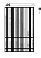
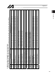
Error No.
(HEX)
800 - 88F
890 - 8AF
8B0 - 8DF
8E0 - 8FF
900 - 93F
940 - 97F
980 - 9AF
9B0 - 9BF
9C0 - 9FF
A00 - A6F
A70 - A9F
AA0 - ACF
AD0 - AFF
B00 - B9F
BA0 - BBF
BC0 - BDF
BE0 - BFF
C00 - CCF
CD0 - CDF
CE0 - CEF
CF0 - CFF
D00 - D8F
D90 - DAF
DB0 - DCF
DD0 - DDF
DE0 - DFF
E00 - E8F
E90 - EBF
EC0 - EDF
EE0 - EFF
FF0 - FBF
FC0 - FCF
FD0 - FDF
FE0 - FEF
Origin of System Error
Assignment
MAIN Application
MAIN Core
PC
TP
MAIN Application
MAIN Core
PC
PC (Update tool)
TP
Flash ACK Time Out
MAIN Core
PC
TP
MAIN Application
MAIN Core
PC
TP
MAIN Application
MAIN Core
PC
TP
MAIN Application
MAIN Core
PC
PC (Update tool)
TP
MAIN Application
MAIN Core
PC
TP
MAIN Application
MAIN Core
PC
TP
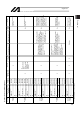
䃁 About Error Level Management
Error level
Secret
level
Message
level
Action
Release
level
Cold start
level
System
failure
level
TP: Teaching Pendant, PC: PC software