
User Manual


9
1. Names of Robot Parts
1
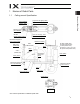
1 Names of Robot Parts
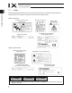
1.1 Ceiling-mount Specification
* The inverse specification is installed upside down.
User connector
Indicator (LED)
I
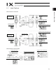
4 joint for user piping, black
I
6 joint for user piping, red
Spacer for user
part installation
BK SW
(Brake-release switch)
I4 joint for user piping, white
I
6 joint for user piping, yellow
Mechanical stopper for
axis 3 (vertical axis)
Axis 4
(rotational axis)
Panel
Ball screw
spline shaft
Cover (arm 2)
Wiring duct
Mechanical stopper for
axis 3 (vertical axis)
Axis 3
(vertical axis)
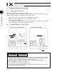
A
xis 2
A
rm 2
End cover (arm 1)
A
rm 1
Base
Cover (base)
Mechanical stopper
for arm 1/arm 2
A
xis 1
Mechanical
stopper for
arm 2
Reference surface
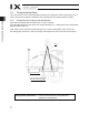
M cable (outside robot)
PG cable (outside robot)
U cable (outside robot)
A
ir tubes (I4: 2 pcs., I6: 2 pcs.)
BK power cable (outside robot)
View B
Cover (arm 1)