
User Manual


28
5. Precautions for Use
5.4 User Wiring and Piping
The robot comes with standard cables and tubes that the user can use in a desired wiring/piping
configuration.
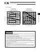
User connector specifications
Rated voltage 3.0 V
Permissible current 1.1 A
Conductor size and number of wires AWG 26 (0.15 mm
2
), 25 wires
Other Twisted-pair cable (1 to 24), shielded
Piping specifications
Normal service pressure 0.8 MPa
4 mm x 2.5 mm, 2 pieces
Dimensions (outer diameter x inner
diameter) and number of tubes
6 mm x 4 mm, 2 pieces
Working medium Air
ALM (indicator) specifications
Rated voltage 24 VDC
Rated current 12 mA
Illumination color Red LED
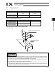
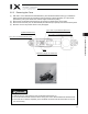
Shape of Y-terminal Spacer for user part installation
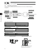
User Connector
D-sub 25-pin
connector for user
wiring (socket),
fixing screw M2.6
A
LM (indicator)
Spacer for user
part installation
BK SW
Brake-release switch
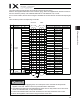
M cable (outside robot)
PG cable (outside robot)
BK power cable (outside robot)
Y-terminal at the end
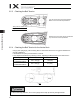
A
ir tube
4 (black, white)
6 (red, yellow)
M4, depth 5
30 N or less
External force applied to the spacers must not
exceed 30 N in the axial direction or 2 Nm in
the rotating direction (for each spacer).
2 Nm or less
Quick joint 6 (red)
Quick joint 4 (black)
Quick joint 6 (yellow)
Quick joint 4 (white)
5.2
3.2
2.6 5.9
7
10
U cable (outside robot)
(cable for user wiring)
Y-terminal at the end