
User Manual

75
7. Specifi cations
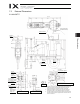
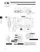
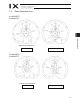
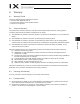
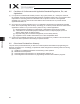
7.2 External Dimensions
IX-HNN-50
(Mechanical end)
3
-
M4, depth 8
Same on
opposite side (*1)
(Mechanical end)
A
rm 1
A
rm 2
stopper
6 quick
air-tube joint
4 quick
air-tube joint
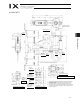
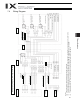
User Connector
D-sub 25-pin connector
for user wiring (socket),
fixing screw M2.6
A
LM (*3)
BK SW
Brake-release switch
Spacer
Outer diameter 7
Height 10 (M4)
Depth 5 (*2)
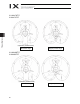
Detailed view of panel (1/2)
Detailed view of arm tip (1/2)
14, hollow
Section A-A
*1: The holes for the 3-M4 screws (depth 8) pierce through the thickness
of the arm’s side wall. If the mounting screws are long, they will
contact the internal parts. Exercise due caution in this regard.
*2: External force applied to the spacers must not exceed 30 N in the
axial direction or 2 Nm in the rotating direction (for each spacer).
*3: The LED operates only when the user provides a circuit that receives
controller I/O output signal and supplies 24 VDC to the LED terminal
in the user connector.
Reference surface
Red
Yell ow
Black
White
Reference
surface
A
rm 2
stopper
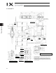
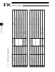
4-11 hole
24 counterbore, depth 5
View B: Detailed view of base installation part
12.5 (installation
center)
235 (recommended
installation dimension)