
User Manual

81
7. Specifi cations
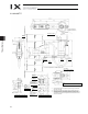
Notes
(1) The actual layout of board connectors varies from this drawing.
(2) Since the brake power circuit is provided on the primary side (high-voltage side), a dedicated 24 V power supply is required for this
circuit. The 24 V power supply for I/O circuits used on the secondary side (low-voltage side) cannot be shared.
(3) To operate the alarm LED, the user must provide a circuit that uses the controller I/O output signal.
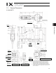
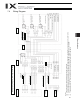
7.4 Wiring Diagram
Wiring/Piping Diagram (Arm Length: 500/600)
Controller
Cable fix cap
(Capcon)
M cable (outside robot)
PG cable (outside robot)
BK power cable (outside robot)
U cable (outside robot)
Brake power
terminals
User wiring
terminals
Inside base
Servo motor for axis 1
(arm 1)
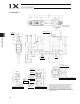
Board
FG (To base)
A
ir joint, red (6)
A
ir joint, yellow (6)
A
ir joint, black (4)
A
ir joint, white (4)
Flexible
cable
Inside arm 2
PG cable (inside robot)
M cable (inside robot)
U cable (inside robot)
Servo motor for axis 2
(arm 2)
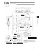
Servo motor with brake
for axis 3 (Z-axis)
Servo motor with brake
for axis 4 (R-axis)
FG (to D-sub housing)
D-sub connector for user wiring (25-pin, socket)
A
larm LED
Brake-release switch for axes 3/4 (Z/R-axes)
A
ir joint, red (6)
A
ir joint, yellow (6)
A
ir joint, black (4)
A
ir joint, white (4)
72