Horizontal Articulated Robot – IX Series Tabletop Type, Clean-room Specification Arm Length 500/600/700/800 IX-NNC50 /60 /70 /80 Operation Manual Fourth Edition
Please Read Before Use Thank you for purchasing an IAI product. This operation manual explains the handling methods, structure and maintenance of this product, among others, providing the information you need to know to use the product safely. Before using the product, be sure to read this manual and fully understand the contents explained herein to ensure safe use of the product. The CD or DVD that comes with the product contains operation manuals for IAI products.
CE Marking If a compliance with the CE Marking is required, please follow Overseas Standards Compliance Manual (ME0287) that is provided separately.
Table of Contents Safety Guide ······················································································································1 Caution in Handling ···········································································································8 1. Names of Robot Parts ································································································9 1.1 1.2 1.3 2.
8. Warranty ·················································································································· 79 8.1 8.2 8.3 8.4 8.5 8.
Safety Guide “Safety Guide” has been written to use the machine safely and so prevent personal injury or property damage beforehand. Make sure to read it before the operation of this product. Safety Precautions for Our Products The common safety precautions for the use of any of our robots in each operation. No.
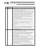
No. 2 2 Operation Description Transportation 3 Storage and Preservation 4 Installation and Start Description When carrying a heavy object, do the work with two or more persons or utilize equipment such as crane. When the work is carried out with 2 or more persons, make it clear who is to be the leader and who to be the follower(s) and communicate well with each other to ensure the safety of the workers.
No. 4 Operation Description Installation and Start Description (2) Cable Wiring Use our company’s genuine cables for connecting between the actuator and controller, and for the teaching tool. Do not scratch on the cable. Do not bend it forcibly. Do not pull it. Do not coil it around. Do not insert it. Do not put any heavy thing on it. Failure to do so may cause a fire, electric shock or malfunction due to leakage or continuity error.
No. 4 5 4 Operation Description Installation and Start Teaching Description (4) Safety Measures When the work is carried out with 2 or more persons, make it clear who is to be the leader and who to be the follower(s) and communicate well with each other to ensure the safety of the workers. When the product is under operation or in the ready mode, take the safety measures (such as the installation of safety and protection fence) so that nobody can enter the area within the robot’s movable range.
No. 6 7 Operation Description Trial Operation Automatic Operation Description When the work is carried out with 2 or more persons, make it clear who is to be the leader and who to be the follower(s) and communicate well with each other to ensure the safety of the workers. After the teaching or programming operation, perform the check operation one step by one step and then shift to the automatic operation.
No. 8 9 6 Operation Description Maintenance and Inspection 10 Modification and Dismantle Disposal 11 Other Description When the work is carried out with 2 or more persons, make it clear who is to be the leader and who to be the follower(s) and communicate well with each other to ensure the safety of the workers. Perform the work out of the safety protection fence, if possible.
Alert Indication The safety precautions are divided into “Danger”, “Warning”, “Caution” and “Notice” according to the warning level, as follows, and described in the Instruction Manual for each model. Level Degree of Danger and Damage Danger This indicates an imminently hazardous situation which, if the product is not handled correctly, will result in death or serious injury.
Caution in Handling 1. Make sure to attach the vertical articulated robot properly by following this operation manual. Using the product with the vertical articulated robot not being certainly retained or affixed may cause abnormal noise, vibration, malfunction or shorten the product life.
1 Names of Parts User connector ALM (indicator) 1. Names of Robot Parts 1.
1. Names of Robot Parts 1.2 Labels The following labels are attached on the robot and controller. Be sure to observe the instructions and cautions written on the labels to ensure the correct use of the robot/controller.
1.3 Label Positions 1.
2 Transportation and Handling 2. Transportation and Handling 2.1 Handling of the Carton Each robot is packed with a controller prior to shipment. When transporting the carton containing the robot and controller, observe the following items and be careful not to drop the carton or apply impact due to forcible contact: x If the carton is heavy, one operator should not attempt to carry it alone. x Place the carton on a level surface if it is to be left there for a while. x Do not climb upon the carton.
2.3 Handling of Individual Components The robot and controller are supplied as a set. Your robot cannot be used with the controller supplied with another robot. When handling multiple robots, be careful not to lose their correct pairings with the controllers. 2.4 Checking after Unpacking After unpacking the carton, check the condition of the robot and other items contained in the carton.
2.5 Transporting the Robot 2. Transportation and Handling When transporting the robot, affix the arms using the supplied arm fixing plate. Additionally, wrap the cables around the base and secure them with gummed tape or other means. Use a dolly, forklift, crane or other appropriate equipment for transportation. When transporting the robot, move it slowly so that it maintains its balance. Also, safeguard the robot against vibration or impact.
3 3.1 Installation Environment and Storage Environment Installation Environment Install the robot in an environment that satisfies the following conditions: Generally, the robot must be installed where the operator need not wear protective gear in order to work. 3.2 Installation Platform The platform on which to install the robot receives a significant reactive force. Be certain the platform has sufficient rigidity to withstand the anticipated force.
3. Installation Environment and Storage Environment 3.3 Storage Environment The storage environment conforms to the installation environment. If the robot is to be stored for a prolonged period of time, be sure the robot will not be exposed to dew condensation. Unless otherwise specified, desiccant is not placed in the carton when shipped. If the robot is to be kept in an environment subject to condensation, provide preventive measures from over the carton or directly to the robot after unpacking.
4. How to Install Shown below is how to install SCARA Robot. 4.1 Installation Posture ż : Available s : Not available Horizontally Oriented Mount Wall-Mount Ceiling-Mount 4.
4.2 4.1 Installing the Robot Install the robot on a level surface. Secure the robot using hex bolts and washers. 4. How to Install Type Bolt size Tightening torque IX-NNC50 /60 M10 60 Nxm IX-NNC70 /80 M12 104 Nxm For the hex bolts, use high-tension bolts with an ISO rating of 10.9 or higher. Warning Caution z Always insert a washer below each bolt. Without a washer, the bolt-bearing surface may sink. z Tighten the hex bolts securely to the correct torque.
4.3 Connecting the Controller The controller connection cables are attached on the robot (standard cable: 5 m, to air-tube joint: 150 mm). Pay attention to the following items when connecting the controller: Connect to the robot of the serial number specified on the robot designation label provided on the front panel of the controller. Robot designation label 4. How to Install Robot serial number Connect the cables securely after confirming that they are free from damage or bent connector pins.
4. How to Install Output voltage: 24 VDC r 10% Current capacity: 20 to 30 W 24 VDC power supply for brake (provided by user) M cable (outside robot) PG cable (outside robot) Tool, control unit, etc. (provided by user) U cable (outside robot) (cable for user wiring) BK power cable (outside robot) Standard cable length: 5 m I4, I6 quick joint (2 pcs. each) To air tube (provided by user) Warning z Before connecting or disconnecting a cable, always turn off the power to the controller.
4.4 4.3 Checking after Installation Once the robot has been installed, check the following items: x Visually check the robot, controller and cables for dents and other abnormalities. x Confirm that the cables are connected properly and that the connectors are inserted securely. 4. How to Install Warning z Failure to perform these checks may result in a malfunctioning robot or a damaged controller or robot.
5 Precautions for Use 5.1 Reference Acceleration/Deceleration Settings Use the robot based on appropriate acceleration/deceleration settings by referring to the following graph: (1) PTP operation (Set using the SEL language commands ACCS and DCLS.) IX-NNC70 /80 Reference acceleration/deceleration settings for PTP operation IX-NNC50 /60 Reference acceleration/deceleration settings for PTP operation 100 Acceleration (%) Acceleration (%) 5.
(2) CP operation (Set using the SEL language commands ACC and DCL.) IX-NNC70 /80 Reference acceleration/deceleration settings for CP operation IX-NNC50 /60 Reference acceleration/deceleration settings for CP operation 1.0 1.0 Acceleration (G) Acceleration (G) 0.5 Reference range for continuous operation setting 5. Precautions for Use Reference range of maximum setting Reference range of maximum setting 0.
5.2 Tools The tool mounting part must have sufficient strength and rigidity, along with adequate fastening power to prevent positional shift. It is recommended that a tool be installed over a split ring, span ring or other appropriate part. A sample configuration of tool installation is given below. The diameter of each tool must not exceed 100 mm. A tool larger than this dimension will interfere with the robot within the robot’s range of movement. 5.
5.3 Carrying Load Load capacity Type Rated load capacity Maximum load capacity IX-NNC50 /60 2 kg 10 kg IX-NNC70 /80 5 kg 20 kg Load’s permissible moment of inertia Type Permissible moment of inertia Remarks IX-NNC50 /60 0.06 kgxm IX-NNC70 /80 0.10 kgxm2 5.
5.4 User Wiring and Piping The robot comes with standard cables and tubes that the user can use in a desired wiring/piping configuration. Quick joint I6 (red) Quick joint I4 (black) User Connector D-sub 25-pin connector for user wiring (socket), fixing screw M2.6 5.
The robot comes with a D-sub 25-pin mating plug for the user connector. Solder a user-supplied cable to the D-sub connector (plug), attach the supplied hood, and then connect to the user connector (socket). Use a shielded cable with an outer diameter of I11 or less. To turn on the indicator, the user must configure a dedicated circuit that uses the controller I/O output signal, etc.
5.5 Suction Rate The robot will conform to cleanliness class 10 when air is sucked at a specified rate from the quick suction joint provided on a side face of the base. x The user must provide the suction device and suction air tube (I12). Model Suction rate (Nl/min) /60 60 IX-NNC70 /80 80 5. Precautions for Use IX-NNC50 Quick suction joint Applicable tube: Outer diameter I12 (inner diameter I8) Caution z The clean room must be designed as a down-flow environment.
6 Inspection/Maintenance 6.1 Inspection/Maintenance Your horizontal articulated robot must be inspected daily and on a regular basis to ensure safe, efficient operation. Perform the necessary inspections after confirming the maintenance/inspection items required for your IAI robot, as defined in this section. The following items must be adjusted at our factory.
6.1.2 Six-Month Inspection Check the following items on the robot every six months. Observe the precautions for work near the robot and for inspection/maintenance/adjustment operations when carrying out each check. Description Check the arm mounting sections for looseness. Robot (If any of the arm mounting sections is loose, tighten the fastening parts securely.) Ball-screw spline Add grease. (AFE Grease by THK or equivalent) Timing belts of axes 3 and • Check the belt tension for axes 3 and 4.
6.2 How to Replace Bellows 6.2.1 IX-NNC-50 /60 Preparation The following tools are required when replacing bellows in the IX-NNC-50 /60 : x Hex wrenches (2, 2.5 and 4 mm) x Replacement bellows (2 units) Turn off the power to the controller. Do not cut off the 24 VDC power supply to the brake. Disassembly (1) Remove the bolts affixing the bellows. (2) Remove the setscrews affixing the top stopper, as well as collar A and gasket A affixing the bellows-turning unit at the bottom. 6.
(3) Remove the stopper at the top and bellows-turning unit at the bottom. (4) Remove the bellows from the robot and separate affixing plates A and B from the bellows. Plate B 6. Inspection/Maintenance Stopper unit at top Plate A Bellows-turning unit at bottom (4 pcs.) Warning Plate B Caution z Performing inspection or maintenance without fully understanding the details of work may result in a serious accident.
Assembly (1) Assemble the bellows by following the disassembly procedure in reverse. (2) Install the bellows by aligning the positioning mark labels attached on the turning unit and collar A. Move the robot’s X-axis, Y-axis, vertical axis and rotational axis to 0, arm length, 0 and 0, respectively, and install and affix the bellows in this position by aligning the arrow position on collar A with the mark on the turning unit. If the marks do not align, reattach the labels. 6.
6.2.2 IX-NNC-70 /80 Preparation The following tools are required when replacing bellows in the IX-NNC-70 /80 : x Hex wrenches (1.5 and 2 mm) x Phillips screwdriver x Replacement bellows (2 units) Turn off the power to the controller. Do not cut off the 24 VDC power supply to the brake. Disassembly (1) Remove the bolts affixing the bellows. (2) Remove the top and bottom bellows units. Collar C 6. Inspection/Maintenance (4 pcs.) Bellows unit (4 pcs.) Gasket D Gasket D Gasket C (4 pcs.
(3) Remove the bellows-turning unit (one unit each at the top and bottom). (4) Remove affixing plate D from the bellows. Bellows-turning unit Plate D Gasket D (4 pcs.) 6. Inspection/Maintenance Plate D Warning Caution z Performing inspection or maintenance without fully understanding the details of work may result in a serious accident. z If inspections are neglected, the drive part may wear prematurely or the robot may malfunction unexpectedly.
6. Inspection/Maintenance Assembly (1) Assemble the bellows by following the disassembly procedure in reverse. (2) Install the bellows by aligning the positioning mark labels attached on the turning unit and collar A. Move the robot’s X-axis, Y-axis, vertical axis and rotational axis to 0, arm length, 0 and 0, respectively, and install and affix the bellows in this position by aligning the arrow position on collar A with the mark on the turning unit. If the marks do not align, reattach the labels.
6.3 How to Check/Adjust Belt Tension 6.3.1 Preparation The following tools are required when checking/adjusting belt tension: x Push-pull gauge (maximum measurement capability of 2 kg) x Hex wrenches (2.5, 3 and 4 mm) x Spanners (5.5 and 8 mm) x Phillips screwdriver x Scale x Pin (I3, 40 to 80 mm in length) Turn off the power to the controller. Do not cut off the 24 VDC power supply to the brake. 6.
6.3.2 Removing the Cover (1) With arms 1 and 2 extended as illustrated below, press the brake-release switch [1] to release the brake and then push down the vertical axis until the stopper contacts the pulley. (2) Remove the countersunk head screws [2], [3] and [4] (four pieces each), in that order. (3) Remove all connectors (UA, UB, BK and LED) and air tubes (four pieces) from the back of the panel. (4) Move the cover to the position shown in the photograph.
6.3.3 Checking the Belt Tension Top view Timing belt for vertical axis Timing belt for rotational axis 6.3.4 Checking the Belt Tension for the Vertical Axis Using a push-pull gauge, push the timing belt for vertical axis with a force of A (gf) and measure the amount of deflection. If the deflection is B (mm), the belt tension is normal. If not, adjust the belt tension by referring to 6.3.6, “Adjusting the Belt Tension for the Vertical Axis.” Type A B /60 340 ~ 410 (gf) 1.
6.3.5 Checking the Belt Tension for the Rotational Axis (1) Remove one setscrew provided on a side face of arm 2. 6. Inspection/Maintenance Remove the screw at the center. (2) Insert a I3 pin in the hole on the side face of arm 2 (pin length: 40 to 80 mm) until the pin lightly contacts the belt, and then mark a point off C (mm) from the surface of arm 2. (3) Using a push-pull gauge, push the pin with a force of D (kgf). The belt tension is normal if the mark on the pin aligns with the surface of arm 2.
6.3.6 (1) (2) (3) (4) (5) Adjusting the Belt Tension for the Vertical Axis Loosen the four M5 nuts [4] slightly, making sure the fastened points do not become overly loose. Loosen the lock nut [5], and then turn the bolt with urethane stopper [6] to tension the belt properly. Check the belt tension by referring to 6.3.4, “Checking the Belt Tension for the Vertical Axis.” Tighten the M5 nuts [4] loosened in step 1, and then tighten the lock nut [5]. Check the belt tension again by referring to 6.3.
6.3.8 Installing the Cover (1) Place the cover on the robot and connect the connectors, cables and air tubes installed as illustrated below. (Absolute reset, as described on the following page, is not required after the belt tension is only checked.) 6. Inspection/Maintenance [2] 4 - M3 x 12 [1] 4 - M3 x 12 Installation position of PG connector PG cable Caution z z z z z z 42 Check the marking tubes to prevent improper connections. Be careful not to bend the air tubes.
[3] 4 - M3 x 12 M cable Installation position of M connector 6. Inspection/Maintenance U cables Installation position of U connectors Be careful not to let them contact the pulley. (2) Install the M4 setscrew on the side face of arm 2. (3) Perform an absolute reset for the rotational axis and vertical axis. This completes the procedure for installation of the cover. (Refer to 6.5, “Absolute Reset Procedure.”) Caution z z z z z z Check the marking tubes to prevent improper connections.
6.4 Battery Replacement 6.4.1 Preparation The following items are required when replacing the batteries: x Phillips screwdriver x New dedicated batteries for IX: AB-3 (4 pieces) 6. Inspection/Maintenance Before replacing the batteries, turn off the power to the controller, control panel and other relevant units. Warning Caution z Performing inspection or maintenance without fully understanding the details of work may result in a serious accident.
6.4.2 Battery Replacement Procedure (1) Remove the countersunk head screws [1] (six pieces) and detach the cover (base). (2) Remove the batteries from the battery holder. (3) Remove the battery connectors and connect new batteries. x After removing the old batteries, quickly connect new batteries (roughly within 5 minutes x number of batteries). x If new batteries are not connected for a longer period, the rotation data will be lost and an absolute reset will become necessary.
(5) Affix the cover (base) using the countersunk head screws [1] (six pieces) (tightening torque: 0.74 Nm). 6. Inspection/Maintenance [1] 6 - M3 x 8 Do not tighten the screws to the specified torque in one go. First tighten the screws to the position shown to the left, and while pushing the cover in the direction of the arrow tighten the screws on both sides evenly to ensure tight sealing. Caution z When installing the cover (base), be careful not to pinch the cables inside.
6.5 Absolute Reset Procedure 6.5.1 Preparation for Absolute Reset The following jig is required when performing an absolute reset: (Included with robot at time of shipment). x Absolute reset adjustment jig Model: JG-1 (IX-NNC50 JG-3 (IX-NNC70 /60 /80 ) ) Plate Pin Absolute reset adjustment jig (type: JG-1) Warning z Performing inspection or maintenance without fully understanding the details of work may result in a serious accident.
6.5.2 Starting the Absolute Reset Menu Open the absolute reset window from the PC software. (2) The absolute reset window opens. x One of three absolute reset screens—for arm 1, arm 2 and rotational axis + vertical axis—is displayed when a corresponding tab is clicked. 6.
6.5.3 (1) Absolute Reset Procedure for Arm 1 or 2 Click the “Encoder Rotation Data Reset1” button. 6. Inspection/Maintenance (2) Click the “Reset Controller Error” button.
6. Inspection/Maintenance (3) Click the “Servo ON” button. (4) Jog the arm to near the reference position (see reference position drawing in step 7), and click the “Jog end” button. (5) Click the “Servo-OFF” button.
(6) Press the emergency-stop switch. (7) Set an adjustment jig (pin) in arm 1 or 2 to fix the arm at the reference position. x Set the jig after confirming that the emergency-stop switch is pressed. x Set the jig after adjusting the arm to the reference position, using the positioning mark label as a guide. x Arm 1 has a cover (not arm 2), which is fixed with setscrews. Remove the setscrews and detach the cover before setting the jig.
6. Inspection/Maintenance (8) Click the “OK” button. (9) Click the “Encoder Rotation Data Reset2” button.
(10) Remove the adjustment jig. x If you are working on arm 1, install the cover and secure it with the setscrews (not required for arm 2). (11) Release the emergency-stop switch. (12) Click the “OK” button. (13) 6. Inspection/Maintenance x An arrow is shown next to the “Home pos. automatic update” button. Do not set this item. (In particular, be sure this item is not set when performing an absolute reset without using a jig).
6.5.4 Absolute Reset Procedure for the Rotational Axis + Vertical Axis Click “Encoder Rotation Data Reset1” button. (2) Click the “Reset Controller Error” button. 6.
Click the “Servo ON” button. (4) Click the “Temp. Standard posture standby” button. x The vertical axis returns to its home position. Exercise caution so as not to be injured by the axis during movement. (5) Jog the rotational axis to the reference position (see reference position drawing in step 8), and click the “Jog end” button. 55 6.
6. Inspection/Maintenance (6) Click the “Servo-OFF” button. (7) Press the emergency-stop switch. (8) Affix the rotational axis at the reference position by setting the plate and pin of the adjustment jig as illustrated below. x Set the jig after confirming that the emergency-stop switch is pressed. x Set the jig after adjusting the rotational axis to the reference position, using the positioning mark label as a guide. x The top face of the stopper should roughly align with the bottom face of arm 2.
Click the “OK” button. (10) Click the “Encoder Rotation Data Reset2” button. 6.
6. Inspection/Maintenance (11) Click the “Home pos. automatic update” button. (12) Remove the adjustment jig. (13) Release the emergency-stop switch. (14) Click the “OK” button.
Click the “Servo ON” button. (16) Click the “Standard posture standby” button. x The vertical axis returns to its home position. Exercise caution so as not to be injured by the axis during movement. (17) Click the “Servo-OFF” button. 59 6.
Click the “Encoder Rotation Data Reset3” button. (19) Click the “Home pos. automatic update” button, and then click “X” in the top right-hand corner to exit the absolute reset window. x Once the absolute reset is complete, be sure to write the flash ROM and reset the controller. 6.
6.5.5 Writing the Flash ROM Following an absolute reset of the rotational axis and vertical axis, the following screen opens when the absolute reset window is closed. Click the “Yes” button. x Clicking “Yes” writes the information in the flash ROM. x The flash ROM must also be written when home position automatic update has been performed for arm 1 or 2. (2) When the writing of flash ROM is complete, the following screen is displayed. Click the “Yes” button.
6.5.6 Resetting the Controller Select “Software Reset” from the Controller menu on the tool bar. (2) Click the “Yes” button. The controller is reset and restarted. 6.
7 Specifications 7.1 Specification Table IX-NNC50 (Arm Length 500, Clean-room Specification) Item Specifications Type IX-NNC50 Degree of freedom Four degrees of freedom Overall arm length 250 Arm 2 length 250 Axis 1 (arm 1) AC servo motor + Speed reducer Axis 2 (arm 2) AC servo motor + Speed reducer Axis 3 (vertical axis) AC servo motor with brake + Belt + Ball-screw spline AC servo motor with brake + Speed reducer + Belt + Spline Axis 1 (arm 1) 7.
Item Specifications Operating environment Ambient temperature/humidity Altitude Temperature: 0 to 40 C, humidity: 20 to 85%RH or less (non-condensing) m 1,000 or less Noise dB 73 Robot weight kg 31.5 Brake power source for main unit W 24V DC ±10% Cleanliness class Class 10 (0.1- m base, with suction) Suction rate (*10) Controller Nl/min 60 Power supply 230 V Allowable supply voltage fluctuation 7.
IX-NNC60 (Arm Length 600, Clean-room Specification) Item Specifications Type IX-NNC60 Degree of freedom Four degrees of freedom Overall arm length 600 mm Arm 1 length Arm 2 length Drive method L-T1 350 250 Axis 1 (arm 1) AC servo motor + Speed reducer Axis 2 (arm 2) AC servo motor + Speed reducer Axis 3 (vertical axis) AC servo motor with brake + Belt + Ball-screw spline Axis 4 (rotational axis) Motor capacity - AC servo motor with brake + Speed reducer + Belt + Spline Axis 1 (arm 1)
Item Specifications Operating environment Ambient temperature/humidity Altitude m 1,000 or less Noise dB 73 Robot weight kg 32.5 Brake power source for main unit W 24V DC ±10% 20W Cleanliness class Class 10 (0.1- m base, with suction) Suction rate (*10) 60 Controller Power supply 230 V Allowable supply voltage fluctuation 7.
IX-NNC70 (Arm Length 700, Clean-room Specification) Item Specifications Type IX-NNC70 Cleanliness class (*10) - L-T1 Class 10 (0.
Item Specifications Operating environment Ambient temperature/humidity Altitude Temperature: 0 to 40 C, humidity: 20 to 85%RH or less (non-condensing) m 1,000 or less Noise dB 74 Robot weight kg 60 Brake power source for main unit W Controller 24V DC ±10% Power supply 230 V Allowable supply voltage fluctuation % 15 A 10 Overvoltage category (IEC60664-1) Category III Pollution degree (IEC60664-1) 7.
IX-NNC80 (Arm Length 800, Clean-room Specification) Item Specifications Type IX-NNC80 Cleanliness class (*10) Degree of freedom 800 mm Arm 1 length 450 Arm 2 length 350 Axis 1 (arm 1) AC servo motor + Speed reducer Axis 2 (arm 2) AC servo motor + Speed reducer Axis 3 (vertical axis) AC servo motor with brake + Belt + Ball-screw spline Axis 4 (rotational axis) Motor capacity L-T1 Four degrees of freedom Overall arm length Drive method - Class 10 (0.
Item Specifications Operating environment Ambient temperature/humidity Altitude Temperature: 0 to 40 C, humidity: 20 to 85%RH or less (non-condensing) m 1,000 or less Noise dB 74 Robot weight kg 62 Brake power source for main unit W Controller 24V DC ±10% Power supply 230 V Allowable supply voltage fluctuation % 15 A 10 Overvoltage category (IEC60664-1) Category III Pollution degree (IEC60664-1) 7.
7.2 External Dimensions IX-NNC50 5 (Mechanical end) 4 - I11 hole I24 counterbore, depth 5 7. Specifications 2-M4 depth 8 (*1) 5 (Mechanical end) Air joint (opposite side) (*4) Reference surface Applicable tube: Outer diameter I12 (inner diameter I8) I6 quick air-tube joint I4 quick air-tube joint Red User Connector D-sub 25-pin connector Black for user wiring (socket), fixing screw M2.
IX-NNC60 7. Specifications 5 (Mechanical end) 4 - I11 hole I24 counterbore, depth 5 2-M4 (*1) 5 (Mechanical end) Air joint (opposite side) Applicable tube: Outer diameter I12 (inner diameter I8) Reference surface I 6 quick air-tube joint I 4 quick air-tube joint Red Section A-A I14, hollow User Connector D-sub 25-pin connector Black for user wiring (socket), fixing screw M2.
IX-NNC70 Air joint (*4) Applicable tube: Outer diameter I12 (inner diameter I8) Arm 2 stopper 7. Specifications 6 (Mechanical end) 4 - I14 hole I30 counterbore, depth 5 Arm 1 Arm 2 stopper 3-M4, depth 8 (same on the opposite side) Sealed by a setscrew (*1) 6 (Mechanical end) PT3/8 plug Reference surface I6 quick air-tube joint I4 quick air-tube joint Red User Connector Black D-sub 25-pin connector for user wiring (socket), fixing screw M2.
IX-NNC80 Air joint (*4) Applicable tube: Outer diameter I12 (inner diameter I8) Arm 2 stopper 7. Specifications 6 (Mechanical end) 4 - I14 hole I30 counterbore, depth 5 Arm 1 Arm 2 stopper 3-M4, depth 8 (same on the opposite side) Sealed by a setscrew (*1) 6 (Mechanical end) PT3/8 plug Reference surface I6 quick air-tube joint I6 quick air-tube joint Red Yellow User Connector D-sub 25-pin connector Black for user wiring (socket), fixing screw M2.
7.3 Robot Operation Area IX-NNC50 7.
7.
77 U cable (outside robot) BK power cable (outside robot) Dedicated batteries for IX: AB-3 PG cable (outside robot) M cable (outside robot) Cable fix cap (Capcon) Air joint, yellow (I6) Air joint, black (I4) Air joint, white (I4) Air joint, black (I4) Air joint, white (I4) Brake-release switch for axes 3/4 (Z/R-axes) Alarm LED D-sub connector for user wiring (25-pin, socket) FG (to D-sub housing) Servo motor with brake for axis 4 (R-axis) Servo motor with brake for axis 3 (Z-axis) Servo motor
78 M cable (inside robot) M cable (outside robot) 5 6 Axis 1 servo motor Axis 2 servo motor Axis 3 servo motor w/ brake Axis 4 servo motor w/ brake M cable (inside robot) M cable (outside robot) 1 2 3 4 5 6 Code name Axis 4 servo motor w/ brake 4 No. Axis 3 servo motor w/ brake 3 /80 Axis 2 servo motor 2 IX-NNC70 Axis 1 servo motor Code name No.
8. Warranty 8.1 Warranty Period One of the following periods, whichever is shorter: y 18 months after shipment from IAI y 12 months after delivery to the specified location y 2,500 hours of operation 8.2 Scope of Warranty Our products are covered by warranty when all of the following conditions are met. Faulty products covered by warranty will be replaced or repaired free of charge: (1) The breakdown or problem in question pertains to our product as delivered by us or our authorized dealer.
8.5 Conditions of Conformance with Applicable Standards/Regulations, Etc., and Applications (1) If our product is combined with another product or any system, device, etc., used by the customer, the customer must first check the applicable standards, regulations and/or rules. The customer is also responsible for confirming that such combination with our product conforms to the applicable standards, etc.
Change History Revision Date April 2011 Description of Revision Second edition A page for CE Marking added Third edition Introduction, Safety Symbols and Safety Precautions are deleted Pg. 1 to 7 Safety Guide added Pg. 8 Caution in Handling added Pg. 18 Brake voltage source capacity from 20W to 30W ĺ changed to 20W Pg. 29 Caution notes added telling to go to see the doctor to have an appropriate treatment when the grease got into an eye Pg.
Manual No.: ME3628-4A (August 2012) Head Office: 577-1 Obane Shimizu-KU Shizuoka City Shizuoka 424-0103, Japan TEL +81-54-364-5105 FAX +81-54-364-2589 website: www.iai-robot.co.jp/ Technical Support available in USA, Europe and China Head Office: 2690 W.