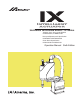
Horizontal Articulated Robot – IX Series Tabletop Type, Arm Length 250/350 IX-NNN-2515H, IX-NNN-3515H Dust-proof/Splash-proof Specification IX-NNW2515H/IX-NNW3515H Clean Room Specification IX-NNC2515H/IX-NNC3515H Operation Manual Sixth Edition
Please Read Before Use Thank you for purchasing our product. This Operation Manual explains the handling methods, structure and maintenance of this product, among others, providing the information you need to know to use the product safely. Before using the product, be sure to read this manual and fully understand the contents explained herein to ensure safe use of the product. The CD or DVD that comes with the product co ntains operation manuals for IAI products.
CE Marking If a compliance with the CE Marking is required, please follow Overseas Standards Compliance Manual (ME0287) that is provided separately.
Table of Contents Safety Guide ............................................................................................................................ 1 Handling Precaution ................................................................................................................ 9 1. Name of Each Part........................................................................................................... 12 1.1 1.2 1.3 Robot .....................................................................
12. Precautions for Use ......................................................................................................... 65 12.1 Setting the Acceleration/Deceleration .........................................................................................65 12.2 Push Force of the Vertical Axis....................................................................................................67 Tools ...................................................................................................
Safety Guide “Safety Guide” has been written to use the machine safely and so prevent personal injury or property damage beforehand. Make sure to read it before the operation of this product. Safety Precautions for Our Products The common safety precautions for the use of any of our robots in each operation. No.
No. 2 2 Operation Description Transportation 3 Storage and Preservation 4 Installation and Start Description When carrying a heavy object, do the work with two or more persons or utilize equipment such as crane. When the work is carried out with 2 or more persons, make it clear who is to be the leader and who to be the follower(s) and communicate well with each other to ensure the safety of the workers.
No. 4 Operation Description Installation and Start Description (2) Cable Wiring Use our company’s genuine cables for connecting between the actuator and controller, and for the teaching tool. Do not scratch on the cable. Do not bend it forcibly. Do not pull it. Do not coil it around. Do not insert it. Do not put any heavy thing on it. Failure to do so may cause a fire, electric shock or malfunction due to leakage or continuity error.
No. 4 5 4 Operation Description Installation and Start Teaching Description (4) Safety Measures When the work is carried out with 2 or more persons, make it clear who is to be the leader and who to be the follower(s) and communicate well with each other to ensure the safety of the workers. When the product is under operation or in the ready mode, take the safety measures (such as the installation of safety and protection fence) so that nobody can enter the area within the robot’s movable range.
No. 6 7 Operation Description Trial Operation Automatic Operation Description When the work is carried out with 2 or more persons, make it clear who is to be the leader and who to be the follower(s) and communicate well with each other to ensure the safety of the workers. After the teaching or programming operation, perform the check operation one step by one step and then shift to the automatic operation.
No. 8 9 6 Operation Description Maintenance and Inspection 10 Modification and Dismantle Disposal 11 Other Description When the work is carried out with 2 or more persons, make it clear who is to be the leader and who to be the follower(s) and communicate well with each other to ensure the safety of the workers. Perform the work out of the safety protection fence, if possible.
Alert Indication The safety precautions are divided into “Danger”, “Warning”, “Caution” and “Notice” according to the warning level, as follows, and described in the operation Manual for each model. Level Degree of Danger and Damage Danger This indicates an imminently hazardous situation which, if the product is not handled correctly, will result in death or serious injury.
8
Handling Precaution 1. Positioning Repeatability Does Not Change Even If the Positioning Band is Changed. Positioning repeatability does not change even if the positioning band is changed. If the positioning band is narrower than the default value, the positioning repeatability does not change, but the time it takes for the positioning complete signal to be output takes longer. The execution of next operation instruction (e.g.
Warning Caution • The robot and controller are very heavy. When transporting the carton containing the robot and controller, handle it with extra care so as not to drop the carton or apply impact due to forcible contact, as it may cause injury or damage to the robot or controller. • Serious injury may result if the carton is dropped onto a person during transportation. • Never stand below the carton as it is hoisted. • Use a carrier device with sufficient loading capacity.
5. Transportation When transporting the robot, affix the arms using the supplied arm fixing plate. Additionally, wrap the cables around the base and secure them with gummed tape or other means. Use a dolly, forklift, crane, or other appropriate equipment for transportation. When transporting the robot, move it slowly so that it maintains its balance. Also, safeguard the robot against vibration or impact. When a crane is used, install the supplied eyebolts on the robot for the pass-through of ropes.
1. Name of Each Part 1. Name of Each Part 1.1 Robot IX-NNN2515H/3515H ALM (indicator) Reference surface 4 user piping (black, red, white; 3 locations) Top cover (arm 1) User connector Spacer for user part installation BK SW (Brake- release switch) Mechanical stopper for axis 3 (vertical axis) Mechanical stopper for arm 1 Mechanical stopper for arm 2 Wiring duct Ball screw spline shaft M cable (outside robot) Cover (arm 2) End cover (arm 1) Air tubes ( 4: 3 pcs.
X-NNW2515H/3515H 1.
IX-NNC2515H/3515H 1.
1.
1. Name of Each Part 1.
2. External Dimensions IX-NNN2515H (Arm Length 250, Standard Specification) Reference surface 2. External Dimensions ALM (indicator) 4 quick air-tube joint (black, red, white; 3 locations) Arm 1 stopper User connector (D-sub 15-pin connector) 4- 9 16, counterbore depth 0.
IX-NNN3515H (Arm Length 350, Standard Specification) 2. External Dimensions ALM (indicator) 4 quick air-tube joint (black, red, white; 3 locations) Arm 1 stopper Reference surface User connector (D-sub 15-pin connector) Arm 2 stopper 4- 9 16, counterbore depth 0.
IX-NNW2515H (Arm Length 250, Dust-proof/Splash-proof Specification) Reference ALM (indicator) surface 92.5 2- 8H10 55 130 Arm 1 stopper 2. External Dimensions 4 quick air-tube joint (black, red, white; 3 locations) BK SW (Brake-release switch) 15 Arm 2 stopper 155 185 160 140 100 User connector 4- 9 16, counterbore depth 0.5 (424.5) 237 (168.5) 249.5 Tapped hole for peripheral installation (4-M4, depth 12) 250 210 (698.5) 74 21 106.5 125 206 16 125 Reference surface 2.
IX-NNW3515H (Arm Length 350, Dust-proof/Splash-proof Specification) 2- 8H10 92.5 Reference surface 55 130 Arm 1 stopper 100 140 User connector 3 4 quick air-tube joint (black, red, white; 3 locations) BK SW (Brake-release switch) Arm 2 stopper 15 155 185 160 2. External Dimensions ALM (Alarm indicator ) 4- 9 16, counterbore depth 0.5 (524.5) 237 (168.5) 249.5 Tapped hole for peripheral installation (4-M4, depth 12) 250 210 (698.5) 8 74 21 106.
IX-NNC2515H (Arm Length 250, Clean Room Specification) 8H10 130 Arm 1 stopper 2. External Dimensions 100 55 160 92.5 140 Reference surface ALM (indicator) 4 quick air-tube joint (black, red, white; 3 locations) User connector (D-sub 15-pin connector) BK SW (Brake-release switch) 15 Arm 2 stopper 155 185 4- 9 16, counterbore depth 0.5 (424.5) (170) 226 Tapped hole for peripheral installation (4-MA, depth 12) 4 (Mechanical end) 249.
IX-NNC3515H (Arm Length 350, Clean Room Specification) 130 User connector (D-sub 15-pin connector) 160 Arm 1 stopper 100 2. External Dimensions 4 quick air-tube joint (black, red, white; 3 locations) 2- 8H10 92.5 55 140 Reference surface ALM (indicator) Arm 2 stopper 15 BK SW (Brake-release switch) Arm 2 stopper 4- 9 16, counterbore depth 0.5 155 185 4 (Mechanical end) 249.5 (170) 226 (524.5) 250 (700) 50 30 125 206 4 (Mechanical end) 16 225 Reference surface 2.5 ST150 106.
3. Robot Operation Area IX-NNN2515H (Arm Length 250, Standard Specification) 139. 5 12 5 130 120 R1 25 3. Robot Operation Area R86.5 R1 25 25 R1 25 R1 1 73. 5 12 7.5 R250 73 . 1 .7 05 R1 R250 9.5 13 0 12 0 13 R1 65 .3 3 65. 160 160 Area of prohibited entry Area of prohibited entry Mechanical stopper position Movement range IX-NNN3515H (Arm Length 350, Standard Specification) .5 139 120 5 12 0 12 R35 0 .7 R162 126.8 R1 25 R1 25 R153.
3.
U14 U15 LED +24V LED G24V FG U13 U1 U2 U3 DWG No.
26 4-axis brake 4-axis motor 4-axis encoder Air joint Black ( 4), Red 4), White ( 4) Brake-release switch for axes 3/4 (Z/R-axes) Alarm LED 3-axis encoder 3-axis motor 3-axis brake M2 PG2 M3 PG3 BK3 M4 PG4 BK4 LED D-sub connector for user wiring (15-oin, socket) 2-axis motor 2-axis encoder PG cable (inside robot) Air tubes 1-axis encoder 1-axis motor Air tubes U cable (inside robot) M cable (inside robot) SW BK4 BK3 OUTPG1 OUTPG2 OUTPG3 OUTPG4 Board M1 M2 M3 M4 24 VDC BAT4
26 27 DWG No. 1068765* U cable (outside robot) BK power cable (outside robot) Dedicated batteries for IX: AB-3 DWG No. 1068764* Female connector HIF 3BA-10D-2,54C (Hirose) PG cable (outside robot) (Phoenix Contact) Plug DWG No.
28 4-axis brake 4-axis encoder 4-axis motor Alarm LED Brake-release switch for axes 3/4 (Z/R-axes) Air joint Black ( 4), Red ( 4), White ( 4), Waterproof connector, 15 pin 3-axis brake 3-axis motor 3-axis encoder 2-axis motor 2-axis encoder 1-axis motor 1-axis encoder Air tubes Air tubes PG cable (inside robot) M cable (inside robot) U cable (inside robot) Board U cable (outside robot) PG cable (outside robot) Controller User wiring terminals Air supply port for air purge Air joint Black (
U cable (outside robot) BK power cable (outside robot) Dedicated batteries for IX PG cable (outside robot) M cable (outside robot) Cable fix cap (Capcon) Air joint, white ( 4) Air joint, red ( 4) Air joint, black ( 4) FG (To base) Board Servo motor for axis 1 (arm 1) Inside base Quick suction joint (tube diameter 12) Flexible cable PG cable (inside robot) FG (to D-sub housing) Electromagnetic brake for axis 4 Servo motor for axis 4 (R-axis) Servo motor with brake for axis 3 (Z-axis) Ser
Machine Harness Wiring Table IX-NNN2515H/3515H (1) PG cables (inside robot) Base end OUT PG4 Mini Universal MATE-N-LOK plug housing 172169-1 (by Tyco Electronics AMP) Same as above Same as above Signal Pin No.
(3) UA and UB cables (outside robot) Base end Tube symbol Connector Double-brazed relay plug DF1110DEP-2C (by Hirose Electric) Signal Pin No. DWG No. 1069444* Arm end Connection Pin Signal No. Connector Tube symbol ID No. Cable D-sub connector XM2D-1501 (by Omron) 4. Wiring Diagram Black AWG22 2 (0.3 mm ) shielded White cable Same as above Un-isolated terminal (round type) F0.
IX-NNW2515H/3515H (1) PG cables (inside robot) Base end Tube symbol Connector Signal Pin No. DWG No. 1068795* Arm end Connection Pin Signal No. Connector Double-brazed crimp socket DF11-8DS-2C (by Hirose Electric) Mini Universal MATE-N-LOK plug housing 172169-1 (by Tyco Electronics AMP) 4. Wiring Diagram Tube ID No.
(3) UA and UB cables (outside robot) Base end Tube symbol Connector Double brazed extension plug DF11-10DEP-2C (by Hirose Electric) Signal Pin No. DWG No. 1068796* Arm end Connection Pin Signal No. Connector D-sub connector XM2D-1501 (by Omron) Tube symbol ID No. Cable 1R/sky blue 1B/sky blue 1R/pink 4.
4.3 Cable Wiring Table IX-NNN2515H/3515H (1) PG cables (outside robot) Robot end Tube symbol Connector Signal Pin No. DWG No. 1068764* Controller end Connection Pin Signal No. Tube symbol ID No. Cable Housing KEC-15P (by JST) Female crimp connector HIF3BA-10D2.54C (by Hirose Electric) 4.
IX-NNW2515H/3515H (1) PG cables (outside robot) DWG No. 1068764* Robot end Tube symbol Connector Signal Pin No. Controller end Connection Pin Signal No. Connector Tube symbol ID No. Cable Housing KEC-15P (by JST) Contact JK-SP2140 (by JST) Connector hood D13A (for 17HE23150-C) (by DDK) 4. Wiring Diagram Female crimp connector HIF3BA-10D2.
(3) UA and UB cables (outside robot) DWG No. 1068765* Robot end Tube symbol Connector 4. Wiring Diagram Double-brazed crimp socket DF11-10DS-2C (by Hirose Electric) Signal Pin No. Controller end Connection Pin Signal No. Connector Un-isolated terminal (Y type) F0.
(3) UA and UB cables (outside robot) DWG No. 1068765* Robot end Tube symbol Connector Connection Pin Signal No. Connector Un-isolated terminal (Y type) F0.
4.4 230 V Circuit Components IX-NNN2515H/3515H, IX-NNC2515H/3515H, IX-NNW2515H/3515H 4. Wiring Diagram No.
5. Option 5.1 Absolute Reset Jig This jig is used to perform an absolute reset in the event that absolute data in the encoder was lost. Model number Remarks JG-2 For arm length 250/350 5. Option 5.2 Flange This flange is used to install a load at the end of the Z-axis arm. Model number Remarks IX-FL-2 For arm length 250/350 5.3 Absolute Data Backup Battery This battery is used to retain absolute data in the encoder. (Set the battery inside the cover of the SCARA robot.
6. Checking after Unpacking After unpacking the carton, check the condition of the product and items included in the carton. 6.1 Items Included in the Carton IX-NNN2515H/3515H No. Item 6. Checking after Unpacking 1 Robot Model number Refer to "How to Read Model Nameplate" and "How to Read Model Number." Remarks Model number Refer to "How to Read Model Nameplate" and "How to Read Model Number.
IX-NNC2515H/3515H No. Item 1 Model number Refer to "How to Read Model Nameplate" and "How to Read Model Number." Robot Remarks 6.2 No. 1 2 3 4 5 6 7 8 9 10 11 6.
6.4 How to Read Model Number 6.
7. Specifications 7.
Item Specifications Three air tubes (outer diameter: φ 4, inner diameter: φ 2.5) (normal service pressure: 0.8 MPa) 7. Specifications User piping Operating Temperature: 0 to 40°C, humidity: 20 to 85%RH or environment Surrounding air temperature/humidity less (non-condensing) Altitude m 1,000 or less Noise dB 71 Robot weight kg 17.
IX-NNN3515H (Arm Length 350, Standard Specification) Item Specifications Type IX-NNN3515H- Degree of freedom Four degrees of freedom Overall arm length 350 mm Arm 1 length Arm 2 length Drive method Axis 1 (arm 1) AC servo motor + Speed reducer AC servo motor + Speed reducer Axis 3 (vertical axis) AC servo motor with brake + Belt + Ball-screw spline Axis 4 (rotational axis) Motor capacity Axis 1 (arm 1) Axis 2 (arm 2) AC servo motor + Belt + Reduction gear + Spline 200 W Axis 4 (rotational axi
7. Specifications Item Operating Surrounding air temperature/humidity environment Altitude m Noise dB Robot weight kg Brake power source for main unit W Controller Power supply Allowable supply voltage % fluctuation Overvoltage category (IEC60664-1) Pollution degree (IEC60664-1) Specifications Temperature: 0 to 40°C, humidity: 20 to 85%RH or less (non-condensing) 1,000 or less 71 18.
7.
Item Specifications Three air tubes (outer diameter: φ 4, inner diameter: φ 2.5) (normal service pressure: 0.8 MPa) Temperature: 0 to 40°C, humidity: 20 to 85%RH or less (non-condensing) 1,000 or less 71 21 DC24VI10% 20W Pressure before expansion of bellows within a range of 0.05 to 0.
IX-NNW3515H (Arm Length 350, Standard Specification) Item Specifications Type IX-NNW3515H- Dust-proof/splash proof performance (*12) Degree of freedom Four degrees of freedom Overall arm length Arm 2 length Drive method 350 mm Arm 1 length 225 125 Axis 1 (arm 1) AC servo motor + Speed reducer Axis 2 (arm 2) AC servo motor + Speed reducer Axis 3 (vertical axis) AC servo motor with brake + Belt + Ball-screw spline Axis 4 (rotational axis) Motor capacity Axis 1 (arm 1) Axis 3 (vertical axis) A
Item Operating Surrounding air temperature/humidity environment Altitude m Noise dB Robot weight kg Brake power source for main unit W Air purge pressure (*11) 7. Specifications Controller (*13) *1 *2: *3: *4 Power supply Allowable supply voltage % fluctuation Overvoltage category (IEC60664-1) Pollution degree (IEC60664-1) *7 *8 *9 *10 *11 *12 *13 DC24VI10% 20W Pressure before expansion of bellows within a range of 0.05 to 0.
7.3 IX-NNC2515H/3515H IX-NNC2515H (Arm Length 250, Cleanroom Specification) Push-in thrust of axis 3 (vertical axis) Permissible load on axis 4 mm W degree mm degree mm/sec degree/sec mm degree sec kg Permissible moment of inertia (*7) Permissible torque Permissible tool diameter (*8) Home detection User wiring Alarm indicator (*9) Suction pipe joint 120 120 150 360 3191 1316 1600 0.010 0.010 0.005 0.44 1 3 111.0 (11.
Item Specifications Three air tubes (outer diameter: φ 4, inner diameter: φ 2.5) (normal service pressure: 0.8 MPa) 7.
IX-NNC3515H (Arm Length 350, Clean Room Specification) Item Specifications Type IX-NNW3515H- Degree of freedom Four degrees of freedom Overall arm length 350 mm Arm 1 length Arm 2 length Drive method Axis 1 (arm 1) AC servo motor + Speed reducer AC servo motor + Speed reducer Axis 3 (vertical axis) AC servo motor with brake + Belt + Ball-screw spline Axis 4 (rotational axis) Motor capacity Axis 1 (arm 1) Axis 2 (arm 2) AC servo motor + Belt + Reduction gear + Spline 200 W Axis 4 (rotational a
Item Specifications Three air tubes (outer diameter: φ 4, inner diameter: φ 2.5) (normal service pressure: 0.8 MPa) 7.
8. Installation Environment and Storage Environment 8.1 8.1.
Dust-proof/splash-proof items y Will not become immersed in liquid. y Free from fine shavings generated by grinding, etc. y Free from cutting oil. y Free form mist of cutting fluid, grinding fluid or other liquids containing sulfur. 8. Installation Environment and Storage Environment About IP65 IP: International Protection rating. IP is a symbol of protection characteristics. 6: Degree of protection against intrusion of solid matter Powder dust will not enter.
8.2 Installation Platform The platform on which to install the robot receives a significant reactive force. Be certain the platform has sufficient rigidity to withstand the anticipated force. The surface on which the robot is fixed must have a thickness of 25 mm or more. The levelness of the robot installation surface must be at least 0.05 mm. Machine tapped holes of the size shown in the table below in the mounting surface of the platform.
9. How to Install Shown below is how to install SCARA Robot. 9.1 Installation Posture ○ : Available × : Not available Wall-Mount ○ × 9.
9.2 Installing the Robot Install the robot horizontally. Use four M3 or M4 hexagonal socket head bolts and washers to securely affix the robot. Model number IX-NNN2515H/3515H IX-NNW2515H/3515H IX-NNC2515H/3515H Bolt size Tightening torque M8 washer 3.2 N-m 9.
9. How to Install For the hexagonal socket head bolts, use high-strength bolts of ISO10.9 or higher. Warning Caution Be sure to use washers. If not, the bearing surface may cave in. Tighten the hexagonal socket head bolts securely to the correct torque. If not, precision may drop and in the worst case the robot may topple and cause an accident.
10. Connecting the Controller The controller connection cables are attached on the robot (standard cable: 3 m). Pay attention to the following items when connecting the controller: • Connect to the robot of the serial number specified on the robot designation label provided on the front panel of the controller.
Output voltage: 24 VDC 10% Current capacity: 20 to 30 W M cable (outside robot) PG cable (outside robot) 24 VDC power supply for brake (provided by user) Tool, control unit, etc. (provided by user) U cable (outside robot) (cable for user wiring) BK power cable (outside robot) Standard cable length: 5 m 4, quick joint (3 pcs.) 10. Connecting the Controller To air tube (provided by user) Warning Before connecting or disconnecting a cable, always turn off the power to the controller.
If you are using an X-SEL-PX/QX controller, you must supply the brake power to the controller in addition to wiring the brake power cable from the SCARA robot. Supply the brake power (+24 V) to the controller as shown in the figure. SCARA robot 3-phase 200 to 230VAC power supply Auxiliary powersupply circuit Upper position: 0 V Lower position: 24 V 10.
11. Checking after Installation Once the robot has been installed, check the following items: Visually check the robot, controller and cables for dents and other abnormalities. Confirm that the cables are connected properly and that the connectors are inserted securely. Warning 11. Checking after Installation Failure to perform these checks may result in a malfunctioning robot or a damaged controller or robot.
12. Precautions for Use 12.1 Setting the Acceleration/Deceleration Set the acceleration/deceleration using the graphs below as a reference. Acceleration deceleration (%) IX arm length 250/350 Reference settings for PTP acceleration/deceleration Maximum setting range Reference range for continuous operation Acceleration deceleration (%) (1) PTP operation (Set using the SEL language commands ACCS and DCLS.
Caution 12. Precautions for Use When PTP operation is performed with the acceleration/deceleration set to 100%, the optimal acceleration/deceleration function adjusts the maximum acceleration/acceleration at which the robot can accelerate/decelerate carrying the load weight set by the WGHT command, to 100%. Be sure to set the mass and inertial moment using the WGHT command. Never set in the WGHT command a value smaller than the load mass installed on the vertical axis.
12.2 Push Force of the Vertical Axis Set the push force of the vertical axis by referring to the graph below. Push force (N) Relationship of push force and push torque limit during positioning Push torque limit during positioning (%) Push-motion operating speed 10 mm/sec Caution 67 12. Precautions for Use Use the PUSH command to perform push-motion operation involving the vertical axis.
12.3 Tools The tool mounting part must have sufficient strength and rigidity, along with adequate fastening power to prevent positional shift. It is recommended that a tool be installed over a split ring, span ring or other appropriate part. A sample configuration of tool installation is given below. Set the tool diameter to 100 mm or less. If the tool diameter exceeds 100 mm, the tool will interfere with the robot within the robot’s operation area.
IX-NNW2515H/3515H, IX-NNC2515H/3515H D-cut surface Center of axis 1 (rotational axis) Tool Span ring, etc. Pressure flange Caution Turn off the power to the controller and robot before installing a tool. If the tool mounting part does not have sufficient strength, it may break while the robot is operating and cause the tool to detach and fly off. If the tool diameter exceeds 80 mm, the tool will contact the robot within the robot’s operation area.
12.4 Transferring Load Model number Rated transferring mass Maximum transferring mass IX-NNN2515H/3515H IX-NNW2515H/3515H 1 kg IX-NNC2515H/3515H Load’s permissible moment of inertia Model number Allowable inertial moment IX-NNN2515H/3515H IX-NNW2515H/3515H IX-NNC2515H/3515H 0.015 kg-m2 3 kg Remarks Both rated and maximum Load offset (from the center of axis 4 (rotational axis)) 40 mm or less 12.
12.5 User Wiring and Piping The robot comes with standard cables and tubes that the user can use in a desired wiring/piping configuration. 12.5.1 IX-NNN2515H/3515H, IX-NNC2515H/3515H IX-NNN2515H/3515H M cable Brake power cable Air tubes ( 4 x 3 pcs.
Shape of Y-terminal User connector specifications Rated voltage 30 V Permissible current 1.1 A Conductor size and number AWG 26 (0.15 mm2), 15 wires of wires Twisted-pair cable (1 to 24), Other shielded Piping specifications Normal service pressure 0.8 MPa Dimensions (outer diameter x inner diameter) and number 4 mm x 2.5 mm, 3 pieces of tubes Working medium Air Spacer for user part installation 7 M4, depth 5 30 N or less 2 N m or less 12.
The user connector comes with the mating D-sub 25-pin plug. The robot comes with a 15-pin plug for the D-sub connector for user wiring. Solder a user-supplied cable to the D-sub connector (plug), attach the supplied hood, and then connect to the user connector (socket). Use a shielded cable with an outer diameter of 11 or less. To turn on the ALM (indicator), the user must configure a dedicated circuit that uses the controller I/O output signal, etc.
12.5.2 IX-NNW2515H/3515H Air supply port for air purge (Applicable tube: Outer diameter 6) BK SW Brake-release switch Quick joint 4 (black) ALM (indicator) Air tubes ( 4 x 3 pcs.) Quick joint 4 (white) User connector Quick joint 4 (red) Spacer for user part installation Panel U cable (outside robot) PG cable (outside robot) Brake power cable (outside robot) M cable (outside robot) Rear Panel 12.
The user connector comes with a mating 16-pin plug. Connector pins 1 to 15 can be used. Pin 16 is connected to a shield wire and cannot be used as a signal wire. Use a cable with an outer diameter of 13.1 to 15.0. The wiring method for the supplied connector is shown below. Clamp nut Setscrew B Washer Cable gasket End bell Coupling nut Barrel Setscrew A [1]: Screw the barrel into the end bell and secure with setscrew A.
User connector pins and corresponding Y-terminals Inside unit Cable Controller side Arm 2 side Connection Y-terminal designation Connection Wire color Orange 1 red Orange 1 black Light gray 1 red Light gray 1 black White 1 red White 1 black Yellow 1 red Waterproof connector, 15 pins Yellow 1 black Pink 1 red Y-terminal Pink 1 black Orange 2 red Orange 2 black Light gray 2 red Light gray 2 black White 2 red White 2 black Indicator (LED) Yellow 2 red 12.
12.6 Suction Rate of Cleanroom Specification IX-NNC2515H/3515H Cleanness class 10 can be achieved by suctioning air at the specified rate through the quick joints for suction provided on the base and rear panel. The suction device and suction air tubes ( 12) are provided by the customer. Suction rate (Nl/min) 80 Quick joint for suction (applicable tube: outer diameter 12, inner diameter 8) 12.
12.7 Air Purge for Dust-proof/Splash-proof Specification IX-NNW2515H/3515H By applying the pressure specified below from the air supply port provided on the side face of the base, the robot will conform to the IP65 dust-proof/splash-proof specification. Service pressure Pressure in a range of 0.3 to 0.6 MPa immediately before the bellows inflates Outer diameter x Inner diameter Outer diameter 6 x Inner diameter 4 Clean, dry air free from compressor oil, etc.
13. Inspection/Maintenance 13.1 Inspection/Maintenance Your horizontal articulated robot must be inspected daily and on a regular basis to ensure safe, efficient operation. Perform the necessary inspections after confirming the maintenance/inspection items required for your IAI robot, as defined in this section. Do not inspect, adjust or repair the robot or controller, replace any of the robot/controller parts, or perform any other operation in a manner not specified in this operation manual.
13.1.1 Daily Inspection Check the following items daily before and after operating the robot. Observe the precautions for work near the robot and for inspection/maintenance/adjustment operations when carrying out each check. Check location Safety cage Robot Cables Emergency-stop switch • • • • • • • • Description Correct the deformation or positional shift of the cage. Confirm that the interlock mechanism is operating properly. Check the robot mounting bolts for looseness.
13.1.3 Yearly Inspection Check the following items on the robot every year. Observe the precautions for work near the robot and for inspection/maintenance/adjustment operations when carrying out each check. Check location Joint bearing for harmonic reduction gear Ball-screw spline Description Check arms 1 and 2 for looseness in the rotating direction and axial direction. (Contact IAI should you find any abnormality.) Check the vertical axis for looseness. (Contact IAI if an abnormality is found.
13.2.2 Replacement Procedure IX-NNN2515H/3515H, IX-NNC2515H/3515H (1) Remove the six low-head cap screws (6 pcs) and remove the rear panel (base). (2) Remove the batteries from the battery holder. (3) Remove the batteries from the extension cables from the battery connectors, and connect new batteries. After removing the old batteries, quickly connect new batteries (roughly within 5 minutes x number of batteries).
12.2.3 Replacement Procedure IX-NNW2515H/3515H (1) Remove the six low-head cap screws (6 pcs) and remove the rear panel (base). (2) Remove the batteries from the battery holder. (3) Remove the batteries from the extension cables from the battery connectors, and connect new batteries. After removing the old batteries, quickly connect new batteries (roughly within 5 minutes x number of batteries).
13.3 Absolute Encoder Reset Method 13.3.1 Preparation for Absolute Reset The following jigs are required to perform an absolute reset. Absolute reset adjustment jigs Model number JG-2 Remarks For arm length 250/300/350 Connect the robot, controller and PC cables so that the robot/controller can be operated using the PC software. Be sure to check the EMG switch operation beforehand.
13.3.2 Starting the Absolute Reset Menu (1) Open the Abs Encoder Reset window from the PC software. (*) Select “Absolute Reset (SCARA Axis) (Y)" if you are using an X-SEL-PX/QX controller. Starting Up Absolute Reset Window 2. The Abs Encoder Reset window opens. One of three absolute reset screens for arm 1, arm 2 and rotational axis + vertical axis is displayed when a corresponding tab is clicked. 13.
13.3.3 Absolute Reset Procedure for Arm 1 or 2 13. Inspection/Maintenance (1) Click the “Encoder Rotation Data Reset1” button. Encoder Multi-rotation Data Reset 1 (2) Click the “Reset Controller Error” button.
(3) Click the “Servo ON” button. Servo ON (4) Jog the arm to near the reference position (see reference position drawing in step (7), and click the “Jog end” button. 13. Inspection/Maintenance Jogging (5) Click the “Servo-OFF” button.
(6) Press the emergency-stop switch. 13. Inspection/Maintenance (7) When performing an absolute reset of arm 1, set the adjustment jig (pin) on arm 1 to secure the arm in its reference position. You can move arm 2 when securing arm 1. When performing an absolute reset of arm 2, set the adjustment jig (pin) on arm 2 to secure the arm in its reference position. You can move arm 1 when securing arm 2. Set the jig after confirming that the emergency-stop switch is pressed.
Positioning mark label for arm 2 Insertion depth: Approx. 20 mm Positioning mark label for arm 1 Insertion depth: Approx. 60 mm Arm 1 (arm length 250/350) Reference Posture for Arm Length 250/350 (Note) For an absolute reset of arm 1 of the IX-NNN2515, slightly bend arm 2 and set the adjustment jig (pin). Warning Always press the emergency-stop switch before setting an adjustment jig. Failure to do so may cause the robot to malfunction and result in a serious accident. 89 13.
(8) Click the “OK” button. Confirmation 13. Inspection/Maintenance (9) Click the “Encoder Rotation Data Reset2” button.
(10) Remove the adjustment jig. If you are working on arm 1, install the cover and secure it with the setscrews. (11) Release the emergency-stop switch. (12) Click the “OK” button. An arrow is shown next to the “Home pos. automatic update” button. Do not set this item. (In particular, be sure this item is not set when performing an absolute reset without using a jig). If you have allowed the home preset value to be updated automatically by mistake, do not write the updated data to the flash ROM.
13.3.4 Absolute Reset Procedure for the Rotational Axis + Vertical Axis 13. Inspection/Maintenance (1) Click “Encoder Rotation Data Reset1” button. Encoder Multi-rotation Data Reset 1 (2) Click the “Reset Controller Error” button.
(3) Click the “Servo ON” button. Servo ON (4) Click the “Temp. Standard posture standby” button. The vertical axis returns to its home position. Exercise caution so as not to be injured by the axis during movement. (5) Jog the rotational axis to the reference position (see reference position drawing in step 8), and click the “Jog end” button. Jogging 93 13.
(6) Click the “Servo-OFF” button. Servo OFF 13. Inspection/Maintenance (7) Press the emergency-stop switch. (8) Affix the rotational axis at the reference position by setting the plate and pin of the adjustment jig as illustrated below. Set the jig after confirming that the emergency-stop switch is pressed. Set the jigs by using the positioning mark as a reference. Make sure the top surface of the stopper roughly matches in height with the bottom surface of arm 2.
Adjust so that a clearance of approx. 4 mm is provided between the stopper’s top face and the bottom face of arm 2. D-cut surface Cause the jig to lightly contact the pin. Positioning mark label for rotational axis D-cut surface (Down view) 13. Inspection/Maintenance Reference Posture for Arm Length 250/350 Warning z Always press the emergency-stop switch before setting an adjustment jig. Failure to do so may cause the robot to malfunction and result in a serious accident.
(9) Click the “OK” button. Confirmation 13. Inspection/Maintenance (10) Click the “Encoder Rotation Data Reset2” button.
(11) Click the “Home pos. automatic update” button. Automatic Refresh of Home Preset Value (12) Remove the adjustment jig. (13) Release the emergency-stop switch. (14) Click the “OK” button. 13.
(15) Click the “Servo ON” button. Confirmation 13. Inspection/Maintenance (16) Click the “Standard posture standby” button. The vertical axis returns to its home position. Exercise caution so as not to be injured by the axis during movement. Standing By at Reference Posture (17) Click the “Servo-OFF” button.
(18) Click the “Encoder Rotation Data Reset3” button. Encoder Multi-rotation Data Reset 3 Automatic Refresh of Home Preset Value 99 13. Inspection/Maintenance (19) Click the “Home pos. automatic update” button, and then click “X” in the top right-hand corner to exit the absolute reset window. After the reset is completed, be sure to perform “Software reset.
14. Warranty 14.1 Warranty Period One of the following periods, whichever is shorter: y 18 months after shipment from our company y 12 months after delivery to the specified location 14.2 Scope of Warranty Our products are covered by warranty when all of the following conditions are met. Faulty products covered by warranty will be replaced or repaired free of charge: (1) The breakdown or problem in question pertains to our product as delivered by us or our authorized dealer.
14.5 Conditions of Conformance with Applicable Standards/Regulations, Etc., and Applications (1) If our product is combined with another product or any system, device, etc., used by the customer, the customer must first check the applicable standards, regulations and/or rules. The customer is also responsible for confirming that such combination with our product conforms to the applicable standards, etc.
Change History Revision Date August 2010 Description of Revision First edition April 2011 Second edition P. 41 Added options “JY (Joint cable specification)” May 2011 Third edition A page for CE Marking added March 2012 Fourth edition P. 1 to 7 Contents added and changed in Safety Guide P. 9 Precautions in Handling Note “Certainly attach the Horizontal Articulated Robot by following this operation manual.” added P. 46, 48, 50, 52, 54 Brake voltage source capacity 20W added to specifications P.
Manual No.: ME3702-6A (January 2013) Head Office: 577-1 Obane Shimizu-KU Shizuoka City Shizuoka 424-0103, Japan TEL +81-54-364-5105 FAX +81-54-364-2589 website: www.iai-robot.co.jp/ Technical Support available in USA, Europe and China Head Office: 2690 W.