Linear Servo Actuator LSA Series Large Type Operating Manual Third Edition Large Types LSA-W21SS, LSA-W21SM LSA-W21HS, LSA-W21HM IAI America, Inc.
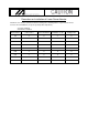
Precaution on Installation of Linear Servo Actuator The linear servo actuator shall be installed according to the following table as a general rule. Please exercise care at installation (except for specially ordered products).
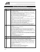
Table of Contents Safety Guide.......................................................................................... Pre-1 1. Foreword .................................................................................................. 1 2. Safety Precautions ................................................................................... 1 2.1 2.2 2.3 Basic Handling ................................................................................................................
8. Wiring of the Cables ............................................................................... 13 9. Precautions for Use................................................................................ 14 9.1 9.2 Actuator Load ................................................................................................................ 14 Home Return ................................................................................................................. 15 9.2.
15. Specifications ....................................................................................... 42 15.1 Actuator ......................................................................................................................... 42 15.2 Cable Wiring Diagram ................................................................................................... 43 15.3 External Dimension Drawing ......................................................................................... 44 15.3.
Safety Guide When designing and manufacturing a robot system, ensure safety by following the safety guides provided below and taking the necessary measures. Regulations and Standards Governing Industrial Robots Safety measures on mechanical devices are generally classified into four categories under the International Industrial Standard ISO/DIS 12100, “Safety of machinery,” as follows: Safety measures Inherent safety design Protective guards --- Safety fence, etc.
Requirements for Industrial Robots under Ordinance on Industrial Safety and Health Work area Outside movement range Work condition Cutoff of drive source During automatic operation Not cut off Cut off (including stopping of operation) Inside movement range Pre-2 Measure Signs for starting operation Installation of railings, enclosures, etc. Sign, etc., indicating that work is in progress Preparation of work rules Measures to enable immediate During stopping of operation teaching, etc. Sign, etc.
Applicable Models of IAI’s Industrial Robots Machines meeting the following conditions are not classified as industrial robots according to Notice of Ministry of Labor No. 51 and Notice of Ministry of Labor/Labor Standards Office Director (Ki-Hatsu No.
Notes on Safety of Our Products Common items you should note when performing each task on any IAI robot are explained below. No. Task Note 1 Model This product is not planned or designed for uses requiring high degrees of safety. selection Accordingly, it cannot be used to sustain or support life and must not be used in the following applications: [1] Medical devices relating to maintenance, management, etc.
No. Task 4 Installation/ startup 5 Teaching Note (2) Wiring the cables Use IAI’s genuine cables to connect the actuator and controller or connect a teaching tool, etc. Do not damage, forcibly bend, pull, loop round an object or pinch the cables or place heavy articles on top. Current leak or poor electrical continuity may occur, resulting in fire, electric shock or malfunction. Wire the product correctly after turning off the power.
No. Task 5 Teaching Note Put up a sign saying “WORK IN PROGRESS” in a conspicuous location. When releasing the brake of a vertically installed actuator, be careful not to pinch your hand or damage the work part, etc., due to the slider dropping by its dead weight. * Safety fences --- Indicate the movement range if safety fences are not provided. 6 Confirmation After teaching or programming, carry out step-by-step confirmation operation operation before switching to automatic operation.
Indication of Cautionary Information The operation manual for each model denotes safety guides under “Danger,” “Warning,” “Caution” and “Note,” as specified below. Level Degree of danger/loss Symbol Danger Failure to observe the instruction will result in an imminent danger leading to death or serious injury. Danger Warning Failure to observe the instruction may result in death or serious injury. Warning Caution Failure to observe the instruction may result in injury or property damage.
Pre-8
1. Foreword Thank you for purchasing an IAI product. This operating manual describes the correct handling, structure, maintenance and other aspects of your actuator. Before using your actuator, be sure to read this operating manual and handle the actuator correctly. Keep this manual with you so that you can reference applicable information whenever necessary. For more complete information on operating the actuator, also peruse the operating manual for your controller. 2. Safety Precautions 2.
3. Warranty 3.1 Warranty Period Warranty period shall be either of the following periods whichever ends first: 18 months after shipment from our factory 12 months after delivery to a specified location 2500 hours of operation time 3.2 Scope of Warranty If a breakdown occurs within the period specified above and is due to the manufacturer's error, we will repair the unit at no cost. However, the following items are not covered by this warranty.
4. Name of Each Part The name of each part of the actuator is specified below. In this manual, the right-left directions of the actuator are indicated by viewing the actuator from its top and also from its home side, with the actuator placed horizontally. “Front” refers to the side opposite to one on which the actuator home is located.
5. Transportation and Handling 5.1 Handling the Actuator by Itself When transporting the actuator by itself, take note of the items specified below. 5.1.1 Handling the Packed Actuator Unless otherwise specified, the actuator of single-axis configuration is packed individually. When transporting or handling the packed actuator, exercise due caution not to hit the package against other object or drop the package. If the package is heavy, the operator must not attempt to carry the package alone.
5.2 Handling the Actuator Assembly Pay attention to the following instructions when transporting an assembly of actuator axes. 5.2.1 Condition of Shipment from IAI (Assembled) The actuators you have ordered are assembled at IAI, after which the assembly receives a shipping inspection and is shipped in an outer frame with skids. The assembly is packed with the sliders securely affixed so that they will not move unexpectedly during transportation.
6. Installation, Storage/Preservation Environment 6.1 Operating Environment The actuator should be set up in an environment, which meets the following criteria: Avoid direct sunlight. Avoid radiant heat from strong heat sources such as a furnace. Ambient temperature should be 0 ~ 40C. The humidity should be less than 85% and there should be no condensation. Avoid exposure to corrosive or combustible gases. The area should have very little dust and be suitable for normal assembly operations.
7. Installation Notes on Installation [Stainless sheet] The stainless sheet is designed very thin (thickness: 0.1 mm) in order to ensure flexibility. Therefore, the stainless sheet is easily dented or scratched. Once dented or scratched, the stainless sheet may break during use. When installing the stainless sheet, pay attention to the following points. Also, be careful not to let a tool or work part drop onto the actuator to dent the exterior of the actuator. Do not press the sheet directly with hands.
7.1 Installing the Actuator Install the actuator on a machined surface or other flat surface of equivalent precision. This linear actuator can be affixed on its top or bottom side. Reamed holes for accepting positioning pins are provided at the back of the base. 7.1.1 Affixing the Actuator on the Top Side of the Base The actuator base has through mounting holes. Use these holes to install the actuator. When installing the actuator, use M8 bolts of strength category 10.
7.1.2 Affixing the Actuator on the Bottom Side of the Base Tapped mounting holes are provided at the back of the actuator base. Use these tapped holes to install the actuator. Tapped hole Tapped hole Tap diameter M8 Caution: Effective tap length 20 mm Tapped holes are not through, so pay attention to the bolt length when selecting bolts.
7.2 Installation Surface Ensure that the frame offers sufficient structural rigidity to prevent generation of vibration. Install the actuator on a machined surface or other flat surface of equivalent precision. The flatness of the installation surface must be 0.05 mm/m or less. Provide sufficient space to allow for maintenance work. The side and bottom surfaces of the actuator base provide reference surfaces used for alignment of slider travel.
7.3 Tightening Screws Use hexagonal socket head bolts (male screws) for installing the base. Use of high-tensile bolts of ISO strength category 10.9 or above is recommended. Provide the following effective engagement length for the bolt and male screw. When the male screw is made of steel When the male screw is made of aluminum Same as the nominal diameter Twice the nominal diameter The recommended tightening torques are as follows.
7.5 Installing a Load on the Slider The slider has tapped holes that can be used to affix a load. The procedure to affix a load on the slider shall conform to the actuator installation procedure. Even when the slider is affixed to move the actuator body, the actuator is also installed using the tapped holes. Two reamed holes are provided in the slider. Use these holes if the load must be installed/removed repeatedly. To fine-tune the squareness, etc., use one of these reamed holes in the slider.
8. Wiring of the Cables Unless otherwise specified, the actuator of single-axis configuration is shipped with a 3 or 5-meter singleaxis cable preassembled with the actuator. Plug the connector at the end of the cable into the controller directly. The single-axis cable has excellent flexibility, but it is not a robot cable. Therefore, avoid storing this cable in a movable wiring duct having a small bending radius.
9. Precautions for Use 9.1 Actuator Load Make sure the load specified in the “Specifications” section is not exceeded. In particular, pay attention to the moment applied to the slider, allowable overhang length, and load. Allowable load moment Unit: Nm (kgfm) LSA-W21SS, LSA-W21SM LSA-W21HS, LSA-W21HM Ma 128.7 (13.1) 275.2 (28.1) Mb 128.7 (13.1) 275.2 (28.1) Mc 128.7 (13.1) 275.2 (28.
9.2 Home Return 9.2.1 Operating Principles of Home Return Home return is performed in the sequence specified below. [1] [2] [3] [4] When a home return command is issued, the moving direction is determined from the specified parameter. A home sensor signal is detected during home return. Upon detection of the home sensor signal, the actuator reverses and subsequently detects a Z-phase signal to recognize this position as the reference point.
9.3 Stainless Sheet The stainless sheet is held in position by the attraction forces of rubber magnets provided on the side covers. If ambient air contains a lot of magnetic substances such as iron powder, these magnetic substances may be attracted to the rubber magnets and enter the space between the stainless sheet and magnets, thereby causing problems. Therefore, avoid using the actuator in an environment where the actuator will come in contact with a high level of magnetic substances.
10. Selection Conditions When using a large linear servo actuator, you must ensure that the actuator satisfies the following two conditions. Condition [1] The thrust required for acceleration must not exceed the maximum thrust of the large linear servo actuator. Condition [2] The thrust during continuous operation must not exceed the rated thrust of the large linear servo actuator. The above conditions are explained by using a trapezoid operation as an example.
10.1 Selection Method Condition [1]: Maximum thrust For the slider to accelerate according to a command, the thrust required for acceleration, or Fa, must be smaller than the maximum thrust of the large linear servo actuator.
Condition [2]: Thrust during continuous operation Confirm that the thrust during continuous operation, or Ft, which also takes into consideration the load and duty, is smaller than the rated thrust of the large linear actuator.
10.2 Example Let’s select a motor by following the procedure in “Selection Method.” Operating conditions Applicable model: Large linear servo actuator LSA-W21SS, LSA-W21SM Speed: 2.5 m/s Acceleration: 29.4 m/s2 (The deceleration is assumed to be the same.) Travel: 2.5 m Slider load: 10 kg The actuator moves back and forth over a stroke of 2.5 m. The above operation pattern can be illustrated by the graph shown to the right.
Test condition [2], “thrust during continuous operation.” Apply the above operation pattern to the aforementioned equation of thrust during continuous operation. Based on the examination result of maximum thrust, the specified acceleration is assumed as 19.6 m/s2. Here, Fa = 512 N, Ff = 120 N, Fd = 272 N, ta = td = 0.127sec, tf = 0.873 sec, t = 1.277 sec (including stabilization time tc of 0.15 sec) From the above, Ft is calculated as 208.02 N.
11. Maintenance and Inspection 11.1 Inspection Items and Schedule Perform maintenance and inspection at the intervals specified below. This schedule assumes that the actuator is operated eight hours a day. If the actuator is operated at a higher utilization, such as when the machine is used continuously day and night, reduce the inspection intervals accordingly.
11.4 Inspecting the Interior With the power supply turned off, turn up the stainless sheet and visually inspect the interior. Check the following items inside the actuator. Actuator Guide Loosening of actuator mounting bolts, etc. Lubrication condition, soiling Visually check the interior condition. What you should focus are entry of dust and other foreign matters and the lubrication condition. Even if grease has turned brown, the actuator is lubricated properly if its traveling surface is glossy.
11.6 Greasing the Guide 11.6.1 Applicable Grease Lithium grease is applied to the guide before shipment. IAI uses the greases specified below. LSA-W21SS, LSA-W21SM AFB-LF Grease (THK) LSA-W21HS, LSA-W21HM Albania EP Grease 2 (Showa Shell Sekiyu K.K.) Other manufacturers are also offering greases equivalent to the above products. Inform your grease supplier of the above products and have them select their product of equivalent properties.
11.6.2 How to Add Grease Before adding grease, turn off the actuator power. 1) Remove the end cover to reveal the right and left grease nipples from which to add grease. End cover Grease nipple 2) 3) Move the slider by hand until it contacts the mechanical end (on the side where the target grease nipple is located). Insert the grease gun into the grease nipple and add grease. Hold the slider with the other hand when adding grease with the grease gun.
12. Troubleshooting 12.1 What to Do When You Suspect a Failure Even when an encoder open error (error code: D12), driver overload error (error code: D0A) or deviation overflow error (error code: C6B) occurs, there may not be a physical breakdown. Before requesting repair of your robot or controller, follow the procedure below to check the location of failure/requiring repair. If the problem persists after the applicable measures have been taken, contact IAI with the detailed condition.
After Start of Operation Encoder open error YES Is there a broken cable? NO YES Is the controller faulty? Check if breakage occurred in the cable track or at the extension cable. [1] If you have an encoder cable in a replacement cable track, try swapping the encoder cables. (In the case of a double-slider system, try swapping the encoder cables in the left and right cable tracks. If the location of the encoder open error changes from the left to right, or vice versa, the applicable cable is broken.
Cable Connection Locations The connection locations of cables on the LSA-W21 linear servo actuator are shown below. Cable in the slider Encoder cable/motor cable in the cable track Encoder extension cable Motor extension cable Location where the cable in the slider is connected to the encoder cable/motor cable in the cable track (The cables are connected in the case. Remove the case cover to access the connection location.
13. Replacement/Adjustment of Stainless Sheet [Required Items] Replacement stainless sheet Hex wrench set Scale Adhesive tape [Notes] 1. Stainless sheet tension Improper tension of the stainless sheet can promote deterioration and wear of the sheet. If the stainless sheet is stretched too much to the extent that the clearance with the slider cover exceeds the specified value of 1 mm, fatigue destruction may result.
13.1 Replacement Procedure for Stainless Sheet 1. Replacing the damaged stainless sheet with a new stainless sheet [1] Check a new stainless sheet to confirm absence of scratches or soiling. [2] Loosen the screws affixing the damaged stainless sheet and remove the sheet retainer plates. [3] Connect the damaged stainless sheet and new stainless sheet using adhesive tape. [4] Slowly pull the end of the damaged stainless sheet so that the sheet slides over the side cover.
13.2 Adjusting the Stainless Sheet Tension [1] First, affix the stainless sheet uniformly on the right and left in a manner free from meandering. (The stainless sheet is held in position by the attraction forces of magnets. Therefore, lift the sheet from one end and then put it back in place toward the same end to achieve better result. Also adjust the stainless sheet from the slider center toward both ends.
[4] Move the slider by hand over its full stroke and see the stainless sheet from above to confirm that the specified dimensions on both sides of the stainless sheet are roughly uniform across the entire length, as shown in the figure. If not, the stainless sheet is skewed. Repeat the adjustment from step [1] to make sure the stainless sheet extends straight. These dimensions on both sides must be roughly uniform.
14. Linear Scale Cleaning Procedure [Required Items for Cleaning] Allen wrenches (4 mm, 3 mm and 2.5 mm across flats) Tweezers Dry cloth Industrial alcohol Marker pen [Procedure] Warning: This actuator uses high-performance rare-earth permanent magnets. Accordingly, anyone who is using a pacemaker or other medical device should not perform this work. Do not bring a watch, mobile phone or any other electronic device susceptible to the magnetic field closer to the actuator.
[2] Remove the stainless sheet and clean the linear scale. So that the original tension can be restored when the stainless sheet is installed again later on, use a marker pen to draw marker lines near the stainless-sheet retainer plates at both ends. Marker lines [3] Use an Allen wrench of 2.5 mm across flats to remove the bolts securing the top stainless-sheet retainer plate. Remove the bolts at both ends of the stainless-sheet retainer plate. Now the stainless sheet can be removed.
(2) Remove the side cover from the side where there is no cable track. Side cover [1] Use an Allen wrench of 2.5 mm across flats to remove the bolts securing the bottom stainlesssheet retainer plate. Remove the bolts at both ends of the bottom stainless-sheet retainer plate. Bottom stainless-sheet retainer plate Side cover Side cover [2] Use an Allen wrench of 4 mm across flats to loosen all bolts securing the side cover.
[3] Remove the side cover. Side cover Before removing the side cover After removing the side cover Once the side cover is removed, you should see the linear scale at the bottom. Linear scale (3) Take a small amount of alcohol in a dry cloth and wipe the linear scale with the cloth in gentle action to remove any soiling. Caution: Do not wipe the linear scale with a strong force. Also, exercise caution not to scratch the scale surface.
(4) [1] Install the side cover to its original condition. Install the side cover you have removed earlier. Side cover Before installing the side cover [2] After installing the side cover Use an Allen wrench of 4 mm across flats to tighten the bolts and secure the side cover. Tightening torque: 411 Ncm (41.9 kgfcm) [3] Use an Allen wrench of 2.5 mm across flats to tighten the bolts at both ends of the bottom stainless-sheet retainer plate to secure the retainer plate.
(5) Install the stainless sheet. [1] Move the slider to near the center of the stroke, and insert the stainless sheet into the slider and guide it through the slider, as shown in the figure. Caution: The permanent magnets have very strong magnetic force, so if you are not careful, the stainless sheet may be attracted to the magnet and become bent to the point where it can no longer be used. Exercise caution. Stainless sheet The slider should be positioned near the center of the stroke.
[3] Pull the stainless sheet from the side not yet secured and align it with the marker lines in the same manner. Loosely tighten the bolts on the top stainless-sheet retainer plate just enough to keep the stainless sheet from moving. Marker line Top stainless-sheet retainer plate Once the stainless sheet is installed as marked, the height of the warped part of the sheet in the slider drops 1.0 mm from the installation surface of the slider cover to prevent contact with the slider cover. Clearance: 1.
[4] Move the slider by hand over its full stroke and see the stainless sheet from above to confirm that the specified dimensions on both sides of the stainless sheet are roughly uniform across the entire length, as shown in the figure. If these dimensions are not uniform across the entire length, the stainless sheet is bent. Remove and install the stainless sheet again. These dimensions on both sides must be roughly uniform. [5] Use an Allen wrench of 2.
[6] Put the slider cover over the slider and tighten the bolts using an Allen wrench of 3 mm across flats to secure the slider cover. Slider cover [7] Finally, move the slider by hand over its full stroke once again to confirm absence of bending and warping of the stainless sheet. Follow the same check method in (5) [4]. Also confirm that the slider is not making noise from contacting the stainless sheet.
15. Specifications 15.1 Actuator Model number Stroke Unit mm Rated thrust N 200 400 Maximum thrust N 600 1200 Maximum speed mm/sec Maximum acceleration/ deceleration Maximum payload capacity Positioning repeatability G Load moment Nm (kgfm) Overhang load length kgf LSA-W21SS, LSA-W21SM LSA-W21SS: 1050 ~ 4155 LSA-W21SS: 730 ~ 3835 3 60 (When used horizontally) 120 (When used horizontally) 0.005 Ma: 128.7 (13.1) Ma: 275.2 (28.1) Mb: 128.7 (13.1) Mb: 275.2 (28.1) Mc: 128.7 (13.
15.2 Cable Wiring Diagram [1] Cable in the cable track (motor cable) (JST) Plug housing: Socket contact: YLP-04V SVF-41T-P0.5A (JST) Receptacle housing: YLR-04VF Pin contact: SYM-41T-P0.5A (Taiyo Electric Co., Ltd.) 300 V EXT-2/2517 4c x 16AWG External diameter: 8.4 Wire Color Red AWG 16 or White equivalent Black Green [2] Signal No. No.
44 8 H7, depth 5 4-M8, depth 20 (Reamer pitch: 0.02) F-M8, depth 20 9, (*1) The cable track may bulge and exceed the following dimensions slightly. Detail view Section J-J Detail view of I of K (1:1) (2:1) (2:1) K 6H7 , depth 10 (Reamer pitch: 0.02) 15.3.1 Slot, depth 5 (I) C-9, depth 13 (Refer to section J-J) 15.
No.
46 Slot, depth 5 (I) C-9, depth 13 (Refer to section J-J) (Minimum slider clearance) 8 H7, depth 5 4-M8, depth 20 (Reamer pitch: 0.02) F-M8, depth 20 K 9, Detail view Section of I J-J (2:1) (1:1) 6H7, depth 10 Detail view of K (2:1) (*1) The cable track may bulge and exceed the following dimensions slightly. 15.3.
No.
48 Slot, depth 5 (I) C-9, depth 13 (Refer to section J-J) 8-M8, depth 20 (Reamer pitch: 0.02) 8 H7, depth 5 F-M8, depth 20 K 9, Detail view Section J-J of I (1:1) (2:1) 2-,6H7, depth 10 Detail view of K (2:1) (*1) The cable track may bulge and exceed the following dimensions slightly. 15.3.
No.
50 Slot, depth 5 (I) C-9, depth 13 (Refer to section J-J) 40 (Minimum slider clearance) 8-M8, depth 20 (Reamer pitch: 0.02) 8 H7, depth 5 F-M8, depth 20 2-,6H7, depth 10 Detail view of I (2:1) K Section J-J (1:1) 9, Detail view of K (2:1) (*1) The cable track may bulge and exceed the following dimensions slightly. 15.3.
No.
Change History Revision Date Description of Revision First edition September 2010 Second edition Page 31 Pages 7 and 16 January 2011 52 Corrected the dimension of the clearance from 1.5 to 1.0 in the drawing Added the precaution; “Do not apply force on the slider cover.” Third edition Removed “Safety Precautions.” Preface-1 to 7: Added “Safety Guide.” P. 6: Storage Environment Storage/Preservation Environment P. 10: Within 0.05 mm Within 0.05 mm/m P.
Catalog No.: ME3645-3A Head Office: 2690 W. 237th Street, Torrance, CA 90505 TEL (310) 891-6015 FAX (310) 891-0815 Chicago Office: 1261 Hamilton Parkway, Itasca, IL 60143 TEL (630) 467-9900 FAX (630) 467-9912 Atlanta Office: 1220 Kennestone Circle, Suite 108, Marietta, GA 30066 TEL (678) 354-9470 FAX (678) 354-9471 website: www.intelligentactuator.com Ober der Röth 4, D-65824 Schwalbach am Taunus, Germany TEL 06196-88950 FAX 06196-889524 IAI (Shanghai) Co., Ltd.