
Manual


3.4 Fieldbus Type Address Map
100
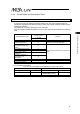
PLC Input (m is PLC input top word address for each axis number).
䎃
䎃
Address m
b15 b14 b13 b12 b11 b10 b9 b8 b7 b6 b5 b4 b3 b2 b1 b0
Current
Position
Lower word
Address m+1
b15 b14 b13 b12 b11 b10 b9 b8 b7 b6 b5 b4 b3 b2 b1 b0
Current
Position
Upper word
(Note)If the target position is a negative value, it is indicated by a two’s complement.
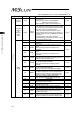
Address m+2
b15 b14 b13 b12 b11 b10 b9 b8 b7 b6 b5 b4 b3 b2 b1 b0
Completed
Position No.
–
–
–
–
–
–
–
–
PM128
PM64
PM32
PM16
PM8
PM4
PM2
PM1
Address m+3
b15 b14 b13 b12 b11 b10 b9 b8 b7 b6 b5 b4 b3 b2 b1 b0
Status Signal
EMGS
CRDY
ZONE2
ZONE1
PZONE
MODES
WEND
MEND
BALM
–
PSFL
SV
ALM
MOVE
HEND
PEND
1 word=16 bit