
Manual


3.4 Fieldbus Type Address Map
123
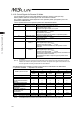
(3) I/O signal assignment
(ON = Applicable bit is “1”, OFF = Applicable bit is “0”)
Signal Type Bit Symbol Contents Details
b15 BKRL
Brake release
ON: Brake release, OFF: Brake activated
3.7 (17)
b14
b13
–
Unavailable –
b12 SON
Servo ON Command
ON: Servo ON, OFF: Servo OFF
3.7 (5)
b11 RES
Reset
A reset is performed when this signal turns ON.
3.7 (4)
b10 STP
Pause
ON: Pause, OFF: Pause Release
3.7 (10)
b9 HOME
Home return
Home-return command with this signal ON,
command carried on till complete even if the
signal is turned OFF on the way
3.7 (6)
b8 CSTR
Positioning start
Movement command executed with this signal
ON, command carried on till complete even if
the signal is turned OFF on the way
3.7 (7)
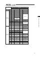
b7 PC128
b6 PC64
b5 PC32
b4 PC16
b3 PC8
b2 PC4
b1 PC2
PLC Input
Control
Signal/
Specified
Position
No.
b0 PC1
Command position number (8-bit binary data)
Available range for Setting: 0 to 255
To operate, it is necessary to have the position
data that the operation conditions are already
set in advance with a teaching tool such as the
PC software.
In this register, indicate the position number the
data is input with a binary number.
Indicating a value out of the range or operating
with a position number with no setting
conducted will generate the alarm code 0A2
“Position Data Error”.
3.7 (29)
b15 EMGS This signal turns ON during an emergency stop 3.7 (2)
b14 ZONE1
“ON” for the current position within the zone 1
set range
The zone range setting is necessary for the
parameter.
3.7 (11)
b13 PSFL
This signal turns ON when the actuator missed
the load in push-motion operation.
3.7 (20)
b12 SV
This signal turns ON when operation standby is
complete (Servo is ON).
3.7 (5)
b11 ALM This signal is ON while an alarm is generated. 3.7 (3)
b10 MOVE This signal is ON while in movement. 3.7 (8)
b9 HEND
This signal turns ON at home return complete
and is kept unless the home position is lost due
to a fact such as an alarm.
3.7 (6)
b8 PEND
This signal turns ON at positioning complete and
is kept ON during a stop with the servo ON, but
does not turn ON when pressing operation is
failed.
3.7 (9)
b7 PM128
b6 PM64
b5 PM32
b4 PM16
b3 PM8
b2 PM4
b1 PM2
PLC Output
Status
Signal/
Completed
Position
No.
b0 PM1
Complete position number (8-bit binary data)
The positioning complete position number is
output in a binary number once getting into the
positioning band after moving to the target
position.
In the case that the position movement has not
been performed at all, or during the movement,
“0” is output. Read it by turning PEND Signal ON
after movement.
3.7 (29)