
User Manual


3.4 Fieldbus Type Address Map
97
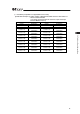
[Combination Example 3] When number of Simple Direct Mode axes is 2 and number of
Direct Indication Mode 6
(Extended Cyclic Setting/Number of Occupied Stations:
8 times/2 stations)
PLC ĺ MSEP MSEP ĺ PLC
Address Description Address Description
RY 000 to 01F Gateway Control RX 000 to 01F Gateway Status
RY 020 to 06F Demand Command RX 020 to 06F Response Command
RY 070 to 07F Cannot be used. RX 070 to 07F Cannot be used.
RY 080 to 17F Cannot be used. RX 080 to 17F Cannot be used.
RWw 00 to 03
Axis No.0 Control
Information
RWr 00 to 03
Axis No.0 Status
Information
RWw 04 to 07
Axis No.1 Control
Information
RWr 04 to 07
Axis No.1 Status
Information
RWw 08 to 0B RWr 08 to 0B
RWw 0C to 0F
Axis No.2 Control
Information
RWr 0C to 0F
Axis No.2 Status
Information
RWw 10 to 13 RWr 10 to 13
RWw 14 to 17
Axis No.3 Control
Information
RWr 14 to 17
Axis No.3 Status
Information
RWw 18 to 1B RWr 18 to 1B
RWw 1C to 1F
Axis No.4 Control
Information
RWr 1C to 1F
Axis No.4 Status
Information
RWw 20 to 23 RWr 20 to 23
RWw 24 to 27
Axis No.5 Control
Information
RWr 24 to 27
Axis No.5 Status
Information
RWw 28 to 2B RWr 28 to 2B
RWw 2C to 2F
Axis No.6 Control
Information
RWr 2C to 2F
Axis No.6 Status
Information
RWw 30 to 33 RWr 30 to 33
RWw 34 to 37
Axis No.7 Control
Information
RWr 34 to 37
Axis No.7 Status
Information
RWw 38 to 3B Cannot be used. RWr 38 to 3B Cannot be used.
RWw 3C to 3F Cannot be used. RWr 3C to 3F Cannot be used.
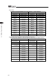
[Combination Example 4] When number of Simple Direct Mode axes is 0 and number of
Direct Indication Mode 8
(Extended Cyclic Setting/Number of Occupied Stations:
8 times/2 stations)
PLC ĺ MSEP MSEP ĺ PLC
Address Description Address Description
RY 000 to 01F Gateway Control RX 000 to 01F Gateway Status
RY 020 to 06F Demand Command RX 020 to 06F Response Command
RY 070 to 07F Cannot be used. RX 070 to 07F Cannot be used.
RY 080 to 17F Cannot be used. RX 080 to 17F Cannot be used.
RWw 00 to 03 RWr 00 to 03
RWw 04 to 07
Axis No.0 Control
Information
RWr 04 to 07
Axis No.0 Status
Information
RWw 08 to 0B RWr 08 to 0B
RWw 0C to 0F
Axis No.1 Control
Information
RWr 0C to 0F
Axis No.1 Status
Information
RWw 10 to 13 RWr 10 to 13
RWw 14 to 17
Axis No.2 Control
Information
RWr 14 to 17
Axis No.2 Status
Information
RWw 18 to 1B RWr 18 to 1B
RWw 1C to 1F
Axis No.3 Control
Information
RWr 1C to 1F
Axis No.3 Status
Information
RWw 20 to 23 RWr 20 to 23
RWw 24 to 27
Axis No.4 Control
Information
RWr 24 to 27
Axis No.4 Status
Information
RWw 28 to 2B RWr 28 to 2B
RWw 2C to 2F
Axis No.5 Control
Information
RWr 2C to 2F
Axis No.5 Status
Information
RWw 30 to 33 RWr 30 to 33
RWw 34 to 37
Axis No.6 Control
Information
RWr 34 to 37
Axis No.6 Status
Information
RWw 38 to 3B RWr 38 to 3B
RWw 3C to 3F
Axis No.7 Control
Information
RWr 3C to 3F
Axis No.7 Status
Information