
User Manual


3.4 Fieldbus Type Address Map
102
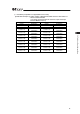
2) CC-Link
(Extended Cyclic Setting/Number of Occupied Stations: 1 times/4 stations)
PLC ĺ MSEP MSEP ĺ PLC
Address Description Address Description
RY 00 to 1F Gateway Control RX 00 to 1F Gateway Status
RY 20 to 6F Demand Command RX 20 to 6F Response Command
RY 70 to 7F Cannot be used. RX 70 to 7F Cannot be used.
RWw 0
Axis No.0 Control
Information
RWr 00
Axis No.0 Status
Information
RWw 01
Axis No.1 Control
Information
RWr 01
Axis No.1 Status
Information
RWw 02
Axis No.2 Control
Information
RWr 02
Axis No.2 Status
Information
RWw 03
Axis No.3 Control
Information
RW 03
Axis No.3 Status
Information
RWw 04
Axis No.4 Control
Information
RWr 04
Axis No.4 Status
Information
RWw 05
Axis No.5 Control
Information
RWr 05
Axis No.5 Status
Information
RWw 06
Axis No.6 Control
Information
RWr 06
Axis No.6 Status
Information
RWw 07
Axis No.7 Control
Information
RW 07
Axis No.7 Status
Information
RWw 08 to 0F Cannot be used. RWr 08 to 0F Cannot be used.
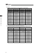
3) PROFIBUS-DPP, EtherNet/IP, MECHATROLINK, EtherCAT
(n is the top node address for each PLC input and output between MSEP and PLC)
PLC ĺ MSEP MSEP ĺ PLC
Node Address
(Byte Address)
Description
Node Address
(Byte Address)
Description
n to n+3 Gateway Control n to n+3 Gateway Status
n+4 to n+15 Demand Command n+4 to n+15 Response Command
n+16,n+17
Axis No.0 Control
Information
n+16,n+17
Axis No.0 Status
Information
n+18,n+19
Axis No.1 Control
Information
n+18,n+19
Axis No.1 Status
Information
n+20,n+21
Axis No.2 Control
Information
n+20,n+21
Axis No.2 Status
Information
n+22,n+23
Axis No.3 Control
Information
n+22,n+23
Axis No.3 Status
Information
n+24,n+25
Axis No.4 Control
Information
n+24,n+25
Axis No.4 Status
Information
n+26,n+27
Axis No.5 Control
Information
n+26,n+27
Axis No.5 Status
Information
n+28,n+29
Axis No.6 Control
Information
n+28,n+29
Axis No.6 Status
Information
n+30,n+31
Axis No.7 Control
Information
n+30,n+31
Axis No.7 Status
Information