
User Manual


3.4 Fieldbus Type Address Map
130
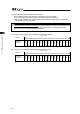
1) Demand command cleared
PLC Output (Address n is the input and output top address for MSEP.)
(Note) Response command does not return.
䎃
Bit
Address b15 b14 b13 b12 b11 b10 b9 b8 b7 b6 b5 b4 b3 b2 b1 b0
n+2
Demand
Command
[0000h]
0 0 0 0 0 0 0 0 0 0 0 0 0 0 0 0
n+3
Data 0
[0]
0 0 0 0 0 0 0 0 0 0 0 0 0 0 0 0
n+4
Data 1
[0]
0 0 0 0 0 0 0 0 0 0 0 0 0 0 0 0
n+5
Data 2
[0]
0 0 0 0 0 0 0 0 0 0 0 0 0 0 0 0
Demand command cleared
n+6
Data 3
[0]
0 0 0 0 0 0 0 0 0 0 0 0 0 0 0 0
䎃
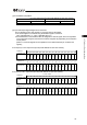
2) Writing of Target Position
PLC Output (Address n is the input and output top address for MSEP.)
(Note) If the writing is finished in normal condition, the same content as the demand command
is returned to the response command.
If an error is generated, an error response is returned. [Refer to this Section 15).]
䎃
䎃
Bit
Address b15 b14 b13 b12 b11 b10 b9 b8 b7 b6 b5 b4 b3 b2 b1 b0
n+2
Demand
Command
[1000h]
0 0 0 0 0 0 0 0 0 0 0 0 0 0 0 0
n+3
Data 0
[Position No.]
–
–
–
–
–
–
–
–
128
64
32
16
8
4
2
1
n+4
Data 1
[Target Position
(Lower word)]
n+5
Data 2
[Target Position
(Upper word)]
Writing of Target Position
n+6
Data 3
[Axis No.]
–
–
–
–
–
–
–
–
–
–
–
–
–
4
2
1
䎃
1 word = 16 bit
1 word = 16 bit