
User Manual


3.4 Fieldbus Type Address Map
140
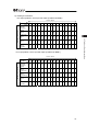
14) Reading of Alarm-issued Axis Number
PLC Output (Address n is the input and output top address for MSEP.)
(Note) If this command is sent, the response command updates with the latest information
until the demand command clear is sent.
䎃
Bit
Address b15 b14 b13 b12 b11 b10 b9 b8 b7 b6 b5 b4 b3 b2 b1 b0
n+2
Demand
Command
[4000h]
0 1 0 0 0 0 0 0 0 0 0 0 0 0 0 0
n+3
Data 0
[0]
0 0 0 0 0 0 0 0 0 0 0 0 0 0 0 0
n+4
Data 1
[0]
0 0 0 0 0 0 0 0 0 0 0 0 0 0 0 0
n+5
Data 2
[0]
0 0 0 0 0 0 0 0 0 0 0 0 0 0 0 0
Reading of Alarm-issued Axis Number
n+6
Data 3
[0]
0 0 0 0 0 0 0 0 0 0 0 0 0 0 0 0
PLC Input (Address n is the input and output top address for MSEP.)
䎃
Bit
Address b15 b14 b13 b12 b11 b10 b9 b8 b7 b6 b5 b4 b3 b2 b1 b0
n+2
Response
Command
[4000h]
0 1 0 0 0 0 0 0 0 0 0 0 0 0 0 0
n+3
Data 0
[0]
–
–
–
–
–
–
–
–
–
–
–
–
–
–
–
–
n+4
Data 1
[Alarm-issued
Axis Number]
1: Alarm
2: Normal
–
–
–
–
–
–
–
–
Status of 7
th
Axis
Status of 6
th
Axis
Status of 5
th
Axis
Status of 4
th
Axis
Status of 3
rd
Axis
Status of 2
nd
Axis
Status of 1
st
Axis
Status of 0
th
Axis
n+5
Data 2
[0]
0 0 0 0 0 0 0 0 0 0 0 0 0 0 0 0
Reading of Alarm-issued Axis Number
n+6
Data 3
[0]
0 0 0 0 0 0 0 0 0 0 0 0 0 0 0 0
1 word = 16 bit
1 word = 16 bit