
User Manual


Chapter 5 I/O Parameter
202
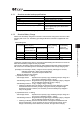
5.1 I/O Parameter List
The categories in the table below indicate whether parameters should be set or not. There are
five categories as follows:
A : Check the settings before use.
B : Use parameters of this category depending on their uses.
C : Use parameters of this category with the settings at shipments leaving unchanged as a
rule. Normally they may not be set.
D : Parameters of the category are set at shipment in accordance with the specification of the
actuator. Normally they may not be set.
E : Parameters of the category are exclusively used by us for convenience of production.
Changing their settings may not only cause the actuator to operate improperly but also to
be damaged. So, never change the setting of the parameters.
Category do not appear on the teaching tool.
Also, the unused parameter numbers are not mentioned in the list.
No.
Category
Name Symbol Unit
(Note 1)
Input Range Default factory setting
Relevant
sections
1 A Positioning width INP
mm
=deg?
0.01 to 999.99
In accordance with
actuator
(Note 2)
5.2 [1]
2 B Jog speed JOGV
mm/s
=deg/s?
0.01 to In accordance
with actuator
In accordance with
actuator
(Note 2)
5.2 [2]
3 C Servo gain number PLGO –
For servo motor
0 to 15
For pulse motor
0 to 31
In accordance with
actuator
(Note 2)
5.2 [3]
4 C Torque filter time constant TRQF – 0 to 2500
In accordance with
actuator
(Note 2)
5.2 [4]
5 C Speed loop proportional gain VLPG – 1 to 27661
In accordance with
actuator
(Note 2)
5.2 [5]
6 C Speed loop integral gain VLPT – 1 to 217270
In accordance with
actuator
(Note 2)
5.2 [6]
7 C Press speed PSHV
mm/s
=deg/s?
1 to actuator's
max. pressing speed
In accordance with
actuator
(Note 2)
5.2 [7]
8 C Press & hold stop judgment period PSWT msec 0 to 9999 255 5.2 [8]
9 C
Current limit value at stopping due to
miss-pressing
PSFC –
0: 1) Current limit during
movement for
servo motor
2) Current limit during
stop for pulse
motor
1: Current limit value
during pressing
0 5.2 [1]
10 B Auto servo-motor OFF delay time ASO1 sec 0 to 9999 0 5.2 [10]
11 B
Stop mode selection
(Note) Function specialized for pulse
motor
SMOD –
0: Full stop
1: Servo stop
0 5.2 [11]
12 B
Current-limiting value at standstill
during positioning
(Note) Function specialized for pulse
motor
SPOW % 1 to 70 35 5.2 [12]
13 C
Current-limiting value during home
return
ODPW %
Pulse motor: 0 to 100
Servo motor: 0 to 300
In accordance with
actuator
(Note 2)
5.2 [13]
14 B
Automatic positioning execution waiting
time
ADWT sec 0.01 to 60 0.01 5.2 [14]
15 A Soft limit LIMM
mm
=deg?
0.01 to 9999.99
Actual stroke on +
side
(Note 2)
5.2 [15]
16 C Home return offset level OFST
mm
=deg?
0.00 to 9999.99
In accordance with
actuator
(Note 2)
5.2 [16]
17 D Home return direction ORG – 0: Reverse, 1: Normal
In accordance with
actuator
(Note 2)
5.2 [17]
18 B Simple absolute unit ETYP –
0: Enabled
(Incremental)
1: Disabled (Simple
Absolute Type)
In accordance with
specification at order
accepted
5.2 [18]
19 A Absolute battery retention time AIP days
0: 20 days
1: 15 days
2: 10 days
3: 5 days
2 5.2 [19]
20 B Position data change password PASS – 0000 to 9999 0000 5.2 [20]