
User Manual


Chapter 5 I/O Parameter
203
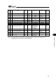
No.
Category
Name Symbol Unit
(Note 1)
Input Range Default factory setting
Relevant
sections
21 B Zone 1+ ZNM1
mm
=deg?
-9999.99 to
9999.99
Actual stroke on +
side
(Note 2)
5.2 [21]
22 B Zone 1- ZNL1
mm
=deg?
-9999.99 to
9999.99
Actual stroke on -
side
(Note 2)
5.2 [21]
23 B Zone 2+ ZNM2
mm
=deg?
-9999.99 to
9999.99
Actual stroke on +
side
(Note 2)
5.2 [21]
24 B Zone 2- ZNL2
mm
=deg?
-9999.99 to
9999.99
Actual stroke on -
side
(Note 2)
5.2 [21]
25 B PIO inch distance IOID
mm
=deg/s?
0.01 to 1.00 0.1 5.2 [22]
26 B Total movement count threshold TMCT times 0 to 999999999 0 (Disabled) 5.2 [23]
27 B Total operated distance threshold ODOT m 0 to 999999999 0 (Disabled) 5.2 [24]
31 B Overload level ratio OLWL % 50 to 100 100 5.2 [25]
32 B Light error alarm output select OALL –
0: Output when
overload warning
1: Overload warning
and message level
alarm output
0 5.2 [26]
33 B Active/Inactive axis select EFCT –
0 (Enabled)
1 (Disabled)
0 5.2 [27]
34 B
Default movement direction for
excitation-phase signal detection
PHSP –
0: Reverse
1: Forward
In accordance with
actuator
(Note 2)
5.2 [28]
35 B Exicitation-phase signal detection time PHSP msec 1 to 999
In accordance with
actuator
(Note 2)
5.2 [29]
36 B Pole sensing type PHSP –
0: Conventional method
1: New method 1
2: New method 2
0 5.2 [30]
(Note 1) The unit [deg] is for rotary actuator and lever type gripper. It is displayed in [mm] in the teaching tools.
(Note 2) The setting values vary in accordance with the specification of the actuator. At shipment, the
parameters are set in accordance with the specification.