Nut Rotary Actuator NS Series Small type: SXMS, SXMM, SZMS, SZMM Medium type: MXMS, MXMM, MXMXS, MZMS, MZMM Large type: LXMS, LXMM, LXMXS, LZMS, LZMM Operating Manual Sixth Edition IAI America, Inc.
Please Read Before Use Thank you for purchasing our product. This Operating Manual explains the handling methods, structure and maintenance of this product, among others, providing the information you need to know to use the product safely. Before using the product, be sure to read this manual and fully understand the contents explained herein to ensure safe use of the product. The CD or DVD that comes with the product contains operation manuals for IAI products.
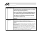
Safety Guide ³6DIHW\ *XLGH´ KDV EHHQ ZULWWHQ WR XVH WKH PDFKLQH VDIHO\ DQG VR SUHYHQW SHUVRQDO LQMXU\ RU SURSHUW\ GDPDJH EHIRUHKDQG 0DNH VXUH WR UHDG LW EHIRUH WKH RSHUDWLRQ RI WKLV SURGXFW Safety Precautions for Our Products 7KH FRPPRQ VDIHW\ SUHFDXWLRQV IRU WKH XVH RI DQ\ RI RXU URERWV LQ HDFK RSHUDWLRQ 1R 2SHUDWLRQ 'HVFULSWLRQ 0RGHO 6HOHFWLRQ 'HVFULSWLRQ Ɣ 7KLV SURGXFW KDV QRW EHHQ SODQQHG DQG GHVLJQHG IRU WKH DSSOLFDWLRQ ZKHUH KLJK OHYHO RI VDIHW\ LV UHTXLUHG VR WKH JXDUDQWHH RI WKH
No. 2 Operation Description Transportation 3 Storage and Preservation 4 Installation and Start Description Ɣ When carrying a heavy object, do the work with two or more persons or utilize equipment such as crane. Ɣ When the work is carried out with 2 or more persons, make it clear who is to be the leader and who to be the follower(s) and communicate well with each other to ensure the safety of the workers.
No. 4 Operation Description Installation and Start Description (2) Cable Wiring Ɣ 8VH RXU FRPSDQ\¶V JHQXLQH FDEOHV for connecting between the actuator and controller, and for the teaching tool. Ɣ Do not scratch on the cable. Do not bend it forcibly. Do not pull it. Do not coil it around. Do not insert it. Do not put any heavy thing on it. Failure to do so may cause a fire, electric shock or malfunction due to leakage or continuity error.
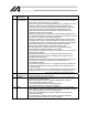
No. 4 Operation Description Installation and Start 7HDFKLQJ Description (4) Safety Measures Ɣ When the work is carried out with 2 or more persons, make it clear who is to be the leader and who to be the follower(s) and communicate well with each other to ensure the safety of the workers.
No. 6 7 Operation Description Trial Operation Automatic Operation Description Ɣ When the work is carried out with 2 or more persons, make it clear who is to be the leader and who to be the follower(s) and communicate well with each other to ensure the safety of the workers. Ɣ After the teaching or programming operation, perform the check operation one step by one step and then shift to the automatic operation.
No. 8 9 Operation Description Maintenance and Inspection 10 Modification and Dismantle Disposal 11 Other Description Ɣ When the work is carried out with 2 or more persons, make it clear who is to be the leader and who to be the follower(s) and communicate well with each other to ensure the safety of the workers. Ɣ Perform the work out of the safety protection fence, if possible.
Alert Indication 7KH VDIHW\ SUHFDXWLRQV DUH GLYLGHG LQWR ³'DQJHU´ ³:DUQLQJ´ ³&DXWLRQ´ DQG ³1RWLFH´ DFFRUGLQJ WR WKH ZDUQLQJ OHYHO DV IROORZV DQG GHVFULEHG LQ WKH ,QVWUXFWLRQ 0DQXDO IRU HDFK PRGHO /HYHO 'HJUHH RI 'DQJHU DQG 'DPDJH 'DQJHU 7KLV LQGLFDWHV DQ LPPLQHQWO\ KD]DUGRXV VLWXDWLRQ ZKLFK LI WKH SURGXFW LV QRW KDQGOHG FRUUHFWO\ ZLOO UHVXOW LQ GHDWK RU VHULRXV LQMXU\ 'DQJHU :DUQLQJ 7KLV LQGLFDWHV D SRWHQWLDOO\ KD]DUGRXV VLWXDWLRQ ZKLFK LI WKH SURGXFW LV QRW KDQGOHG FRUUHFWO\ FRXOG
Handling Precautions 1. Handling the Actuator by Itself 1.1 Handling the Packed Actuator Unless otherwise specified, the actuator of single-axis configuration is packed individually. When transporting or handling the packed actuator, exercise due caution not to hit the package against other object or drop the package. x If the package is heavy, the operator must not attempt to carry the package alone. x When setting down the package, place it horizontally. x Do not step onto the package.
2. Handling the Actuator Assembly Pay attention to the following instructions when transporting an assembly of actuator axes. 2.1 Condition of Shipment from IAI (Assembled) The actuators you have ordered are assembled at IAI, after which the assembly receives a shipping inspection and is shipped in an outer frame with the base of a squared log. The assembled actuator is packed with the sliders securely affixed so that they will not move unexpectedly during transportation.
Table of Contents 1. Names of the Parts.................................................................................................... 1 2. Exterior Views ........................................................................................................... 2 2.1 Actuator Types................................................................................................................. 2 2.1.1 SXMS ................................................................................................
9. Connecting to the Controller.................................................................................... 35 10. Notes on Operation ................................................................................................. 38 10.1 Load Applied to the Actuator ......................................................................................... 38 10.2 Use your actuator at duties not exceeding the calculated reference duty...................... 39 10.3 About Home Return..................
1. Names of the Parts In this manual, the left and right sides are indicated by looking at the horizontally positioned actuator from the motor in the top view. The front side corresponds to the opposite motor end. (Note) On an actuator of single-slider specification, the motor end corresponds to the side where the IAI logo is shown.
2. Exterior Views 2.1.1 SXMS 2-6H7, reamed, depth 10 Reamed pitch r0.02 2. Exterior Views 2.
SXMM 2. Exterior Views Reamed pitch r0.02 2.1.2 80 (minimum distance between sliders) 4-M6, depth 20 80 (minimum distance between sliders) 2-I6H7, reamed, depth 10 Stroke + 30 Stroke + 20 B x 150 pitch B x 150 pitch 2-I6H7, reamed, depth 5 P Detail View of Base E-I7, through I11, counterbore, Mounting Hole Scale 1:1 depth 8 (from opposite side) Stroke Slot, depth 5 Detail View of P (2 locations) Scale 2:1 (Note) The effective stroke is calculated as “Nominal stroke + 30 mm.
SZMS 2. Exterior Views 2.1.3 Reamed pitch r0.
SZMM 2. Exterior Views Reamed pitch r0.02 2.1.
MXMS 2. Exterior Views 2.1.5 Reamed pitch r0.
2.1.6 MXMM 2. Exterior Views Reamed pitch r0.
MXMXS 2. Exterior Views 2.1.7 Reamed pitch r0.
MZMS 2. Exterior Views 2-I6H7, reamed, depth 10 Reamed pitch r0.02 2.1.8 4-M8, depth 25 4-M6, depth 20 Stroke +10 B x 200 pitch B x 200 pitch 2-I8H7, reamed, depth 10 P E-I9, through I16, counterbore, Detail View of depth 10 Base Mounting (from opposite side) Hole Scale 1:1 Q Detail View of Q: T-groove in Base Scale 2:1 Stroke Slot, depth 10 Detail View of P (2 locations) Scale 1:1 (Note) The effective stroke is calculated as “Nominal stroke + 10 mm.
MZMM 2. Exterior Views 2.1.9 Reamed pitch r0.
LXMS 2. Exterior Views (Reamed pitch) 2.1.
LXMM (Reamed pitch) 2. Exterior Views 2.1.
LXMXS 2. Exterior Views (Reamed pitch) 2.1.
LZMS (Reamed pitch) 2. Exterior Views 2.1.
LZMM 2. Exterior Views (Reamed pitch) 2.1.
3. [1] Cable Drawings Motor cable 3. Cable Drawings Model: CB-X-MA (Front view) (Front view) Actuator end Controller end Wire size [2] Color Signal Signal Signal Color Green Red Red White White Black Black Green Wire size (crimped) Encoder cable Model: CB-X2-PA (Front view) Controller end Wire size Color Actuator end (Front view) Plug housing: XMP-09V (JST) Socket contact: BXA-001T-P0.
[3] Encoder cable with LS Model: CB-X2-PLA 3.
4. Options 4.1 Cable track Installation Direction 4. Options With single sliders, you can specify an option corresponding to the desired direction in which the cable track is installed.
4.2 Extended Cable track The standard cable track that comes pre-assembled on large nut rotary actuators is used exclusively for the wirings of the nut rotary actuator and has no space for accommodating any additional wirings the user may require. Accordingly, extended cable tracks are provided as options to accommodate user wirings. The standard cable tracks that come with small and medium types have a space to accommodate user cables. Refer to the following page. 4.
4. Options The available spaces in the standard cable tracks for small and medium types are shown below. Available space Medium types: MXMS, MXMM, MXMXS, MZMS, MZMM Available space Small types: SXMS, SXMM, SZMS, SZMM The points to note when storing cables/hoses in small type and large type cable tracks are specified below: [1] Provide a minimum clearance of 2 mm between the outer diameter of the cable/hose bundle and the interior wall of the cable track, and also between the individual cables and hoses.
4.3 Creep Sensor 4. Options This sensor is used to perform home return at high speed. Since home return is implemented by causing the slider to contact the stroke-end stopper and then reverse its direction, the home return speed is kept to a range of 10 to 20 mm/sec. If the axis stroke is longer, the time required for home return becomes longer. The creep sensor is a proximity sensor used to reduce the time required for home return.
5. Reviewing Contents after Unpacking After unpacking the actuator package, check the condition of the product as well as the items included in the package. 5. Reviewing Contents after Unpacking 5.1 Included Items No. Item 1 Actuator Remarks Refer to “How to Read Model Nameplate” and “How to Read Model Name.” Accessories 2 Motor cable 3 Encoder cable 4 Operation manual Standard specification With limit switch CB–X-MA CB–X2-PA CB–X2-PLA 5.2 Operation Manuals Relating to This Product No.
5.
6. Specifications 6.1 Small type 12 400 to 800 70.8 720 0.3 12 230 to 830 70.8 720 0.3 SZMS, vertical specification 12 420 to 820 70.8 600 0.3 G 0.8 0.8 0.7 0.7 kgf 15 (When used horizontally) 15 (When used horizontally) 3 (When used vertically) 3 (When used vertically) kgf 0.5 0.5 0.5 0.
6.2 Medium type Model Unit Lead Stroke Rated thrust Maximum speed Rated acceleration*3 Maximum *3 acceleration/deceleration Loading capacity at rated acceleration*2 mm N mm/sec G MXMS, horizontal specification MXMM, horizontal specification 20 500 to 1500 170.9 1200 0.3 30 500 to 1500 113.9 1800 0.3 20 330 to 1530 170.9 1200 0.3 30 330 to 1530 113.9 1800 0.3 0.8 1.0 0.8 1.
Model Unit 6SHFL¿FDWLRQV Lead Stroke Rated thrust Maximum speed *3 Rated acceleration Maximum *3 acceleration/deceleration Loading capacity at rated acceleration*2 mm N mm/sec G 20 1600 to 2200 170.9 1200 0.3 30 1600 to 2200 113.9 1800 0.3 MZMS, vertical specification 20 510 to 810 170.9 1000 0.3 0.3 0.3 0.5 MXMXS, horizontal specification G MZMM, vertical specification 30 300 to 800 170.9 1000 0.3 0.
6.3 Large type Model Unit Lead Stroke Rated thrust Maximum speed *3 Rated acceleration Maximum acceleration/deceleration*3 Loading capacity at rated *2 acceleration mm N mm/sec G LXMS, horizontal specification LXMM, horizontal specification 20 500 to 2200 340.1 1300 0.3 40 500 to 2200 170.0 2400 0.3 20 250 to 2250 340.1 1300 0.3 40 250 to 2250 170.0 2400 0.3 1.0 1.0 1.0 1.
Model Unit 6SHFL¿FDWLRQV Lead Stroke Rated thrust Maximum speed Rated acceleration*3 Maximum acceleration/deceleration*3 Loading capacity at rated acceleration*2 mm N mm/sec G 20 2300 to 3000 340.1 1300 0.3 40 2300 to 3000 170.0 2400 0.3 LZMS, vertical specification 20 500 to 1000 340.1 1000 0.3 0.3 0.3 0.8 LXMXS, horizontal specification G LZMM, vertical specification 20 250 to 950 340.1 1000 0.3 0.
7. Operating and Storage Environment 7.1 Operating Environment The actuator should be set up in an environment, which meets the following criteria: In general, the environment should be one in which an operator can work without protective gear. 7.2 Storage Environment x The storage environment should be similar to the operating environment. x If the actuator is stored for a long period, pay special attention to prevent bedewing. x We do not include moisture absorption agents when shipping the unit.
8. Installation How to install the actuator is explained based on a single-axis configuration. 8.1 Installing the Actuator The surface on which to install the actuator shall be a machined surface or a flat surface having equivalent accuracy. 8. Installation x Mounting holes are provided in the actuator base, so use these holes to install the actuator. Use M8 bolts conforming to strength category 10.9 or above, together with the dedicated washers that came with the actuator (to prevent buckling).
x On an actuator of single-slider specification, the home is located on the end where the IAI logo is attached on the side face of the screw cover. Pay attention to the direction when installing the actuator. Model nameplate Counter-home side Home side 8.
8.2 Installation Surface 8. Installation x The frame shall have sufficient structural rigidity to prevent vibration. x The surface on which to install the actuator shall be a machined surface or a flat surface having equivalent accuracy, where the surface flatness shall be within r0.05 mm. x Provide the space needed to carry out maintenance work. x The side and bottom faces of the actuator base are used as reference surfaces for slider travel alignment.
8.3 Installing a Load on the Slider x Tapped holes are provided in the slider, so use these holes to securely affix a load. The affixing method varies depending on how the actuator is installed. x If the slider is affixed to move the actuator body, also use the slider’s tapped holes for installation. (When installing a heavy object, also use pins.) x Two reamed holes are provided in the slider, so use these holes if position accuracy must be maintained after removal/reinstallation.
8.4 Installing the Connector Box, and T-groove 8. Installation On the nut rotary actuators of medium and large types, M4 T-grooves are provided on the side face of the base for installing the connector box, cable track receiver and other items required by the combination specification. (See the figure below.) If the combined specification requires a wiring kit, use this T-slot to install the kit.
9. Connecting to the Controller How to wire the actuator with the controller is explained based on a single-axis configuration. If you ordered a single-axis actuator, your actuator should have a 3-meter or 5-meter single-axis cable preassembled with the actuator body. Plug the connector at the end of the cable directly into the connector. If the actuator is of multi-slider specification, make sure the connectors are joined correctly by referring to the marker tubes (M1, M2, PG1, PG2) at the cable ends.
When designing an application system using actuators and controllers, incorrect wiring or connection of each cable may cause unexpected problems such as a disconnected cable or poor contact, or even a runaway system. This section explains prohibited handling of cables. Read the information carefully to connect the cables properly. x Do not cut any of the cables to reduce its length or reconnect the cut cable with other cable to extend the wiring length or for any other purpose.
x When fixing the cable, provide a moderate slack and do not tension it too tight. Do not use a spiral tube where the cable flexes frequently. x Separate the I/O and communication lines from the power and drive lines. Do not guide them together in the duct. Duct I/O line (Flat cable, etc.) Follow the instructions below when using a cable track.
10. Notes on Operation 10.1 Load Applied to the Actuator x The load specified in the specification table must not be exceeded. In particular, pay attention to the moments applied to the slider, allowable overhang length and loaded mass. x If the actuator is used as the Y-axis in a cantilever X-Y robot, the base becomes vulnerable to deformation. Accordingly, keep the Ma and Mc moments to one half the rated moment or below. (Refer to the figure below.
10.2 Use your actuator at duties not exceeding the calculated reference duty. “Duty” indicates the utilization rate of an actuator (time during which the actuator operates in a cycle). Use your actuator at duties not exceeding the reference duty calculated as follows. If the actuator is used at duties exceeding the reference duty, the actuator may receive an overload or its motor may generate heat. In extreme cases, motor damage or other undesired result may follow.
10.3 About Home Return 10.3.1 Operating Principles of Home Return This actuator implements a home return in the following steps: [1] [2] [3] [4] Upon receiving a home return command, the actuator determines the moving direction based on the specified parameter. The actuator detects a home sensor signal during the return operation.
11. Maintenance 11.1 Maintenance Schedule Perform maintenance work according to the schedule below. The schedule is set assuming eight hours of operation a day. When the operation time is long such as 24-hour operation, shorten the maintenance intervals as needed.
11.4 Internal Inspection Turn off the power and remove the screw cover to visually inspect the interior. Check the following items in the internal inspection. Body Guide Ball screw Loose mounting bolts? Lubrication condition okay? Soiling? Lubrication condition okay? Soiling? 11. Maintenance Visually check the condition inside the actuator. Specifically, check for entry of dust and other foreign matters and the lubrication condition.
An example of how to check the interior of large types is given below. Follow the same procedure to check the interior of small and medium types. [1] Use an Allen wrench of 1.5 mm in width across flats to take out the end cover. [2] Remove the screw cover using an Allen wrench of 2.0 mm across flats. (For small types, use an Allen wrench of 1.5 mm in width across flats.) [3] Check the interior. Guide 11.
11.5 Internal Cleaning x Clean each area using a soft cloth, etc. x Do not blow compressed air onto the internal parts, as dust may enter through gaps and openings. x Do not use petroleum solvent, neutral detergent or alcohol. 11.6 Greasing the Guide 11.6.1 Applicable Grease Lithium grease is used. The following grease has been applied prior to shipment. Idemitsu Kosan Daphne Eponex Grease No.2 11. Maintenance Other manufacturers offer different greases equivalent to the above product.
11.6.2 How to Add Grease (1) Small type: SXMS, SXMM, SZMS, SZMM Medium type: MXMS, MXMM, MXMXS, MZMS, MZMM A grease nipple is provided inside the home-side stopper of the slider, so add grease from this grease nipple. Use an Allen wrench of 1.5 mm in width across flats to remove the two screws and take out the end cover on the home side. [2] [3] Move the slider all the way to the home side.
z Small type: SXMS, SXMM, SZMS, SZMM Grease nipple Grease nipple z Medium type: MXMS, MXMM, MXMXS, MZMS, MZMM 11. Maintenance Grease nipple [4] [5] [6] 46 (Mid-support specification: 105) Move the slider back and forth several times by hand. Repeat the above steps to add grease. Use a waste cloth, etc., to wipe off grease that has overflowed from the slider.
(2) Large type: LXMS, LXMM, LXMXS, LZMS, LZMM Two grease nipples are found, one each on the right and left sides of the slider. Apply grease from these nipples. [1] Using a grease gun, apply grease from the grease nipples located on the end faces of the slider. (Refer to the figure below for the positions of grease nipples.) 11. Maintenance Grease nipple positions on the slider [2] [3] [4] Move the slider back and forth several times by hand. Repeat the above steps to apply more grease.
11.7 How to Add Grease to the Ball Screw 11.7.1 Applicable Grease The following lithium grease has been applied prior to shipment. Kyodo Yushi Multemp LRL 3 This grease has excellent properties including low heat generation and is suitable for ball screws. Warning Never use fluorine grease. If fluorine grease is mixed with lithium grease, lithium grease will lose its intended lubrication property and the machine may be damaged. 11.7.2 How to Apply Grease 11.
11.8 Adjusting the Mid-support Wire Tension [Items required for adjustment] Allen wrenches Tension gauge (capable of exerting a push force of at least 1 kg (9.8 N)) [Procedure] [1] Remove the end cover using an Allen wrench of 1.5 mm across flats. Remove the screw cover using an Allen wrench of 2.0 mm across flats. [3] Loosen the two screws (M3 x 5) affixing one wire hook (base side) of the mid-support wire located at the center of the base, so that the wire hook can be moved.
[4] Use a tension gauge to push the loosened wire hook with the specified push force, and tighten the two wire hook screws (M3 x 5). 11. Maintenance Specified push force: 9.31 to 9.8 N Tighten the screws while pushing the wire hook with the specified push force. Tightening torque: 1.5 (N•m) [5] After the check, assemble the parts by following the same steps in reverse.
11.9 Replace the Mid-support Wire [Items required for replacement] Mid-support wire Model: WR-LXMXS-(stroke) Wire hook (base side): As a replacement when the wire catch of the original hook is deformed. Wire hook (motor side): As a replacement when the wire catch of the original hook is deformed. Allen wrenches Tension gauge (capable of exerting a push force of at least 1 kg (9.8 N)) [Procedure] [1] Remove the end cover using an Allen wrench of 1.5 mm across flats. 11.
[3] Loosen the two screws (M3 x 5) affixing one wire hook (base side) of the mid-support wire located at the center of the base, so that the wire hook can be moved. Loosen the screws for only one wire hook on either the home side or counter-home side. Wire hook (base side) 11. Maintenance Loosen the wire hook on one side.
[4] Remove the wire from the wire hook whose screws have been loosened. Remove the wire from the wire hook (base side). Next, pull out the wire through the delrin bearing at the mid-support and remove it from the wire hook (motor side). Remove the wire. Pull out the wire through the delrin bearing. 11. Maintenance Remove the wire. [5] Follow the same steps to also remove the wire from the wire hook (base side) whose screws have not been loosened.
[6] Hook one end of the replacement wire on the wire hook (base side) whose screws have not been loosened. Guide the other end of the wire under the motor and bring it to the mid-support, and hook the wire on the delrin bearing at the mid-support. Next, pull the wire further to the motor and hook it on the wire hook at the motor. Hook one end of the replacement wire on the wire hook. 11. Maintenance Guide the replacement wire under the motor.
When hooking the wire in step [6], you may find the wire catch of the hook (motor side) deformed. In this case, replace the wire hook as follows: Replace the wire hook with a replacement wire hook (motor side), and tighten the two screws (M3 x 6). Tighten the screws. Tightening torque: 1.5 (N•m) 11. Maintenance [7] Follow the same steps to also attach the wire to the wire hook (base side) whose screws have been loosened.
[8] Use a tension gauge to push the wire hook (base side) whose screws have been loosened with the specified push force, and tighten the two wire hook screws (M3 x 5). 11. Maintenance Specified push force: 9.31 to 9.8 N Tighten the screws while pushing the wire hook with the specified push force. Tightening torque: 1.5 (N•m) [9] After the check, assemble the parts by following the same steps in reverse.
12. Troubleshooting 12.1 What to Do When an Error Occurs If an encoder open error, driver overload error, deviation overflow error or any other error occurs, do not hastily determine that the robot or controller is faulty. Refer to the information below and check if the problem can be corrected by the applicable procedure. If the problem still persists after the troubleshooting procedure, contact IAI and provide us with detailed information regarding the problem condition. 12.
12.3 Driver Overload Error (Error Code: D0A) Driver overload error High operation duty? Review the operating conditions by referring to the operating manual (10, “Selection Conditions”). Slider receiving an external force or resistance? Remove the external force or resistance. Turn off the power and move the slider by hand to check. 12. Troubleshooting Mechanical movement of the actuator heavy? Repair If a replacement controller is available, swap the controllers and check the operation.
12.4 Deviation Overflow Error (Error Code: C6B) Deviation overflow error Excessive acceleration/deceleration relative to the load capacity? Reduce the acceleration/deceleration. Broken motor cable? Replace the motor cable. Connector wiring error? [1] The connector is not securely connected. [2] Loose pins. [3] Wrong addresses (the motor and encoder connectors are connected in reverse). Remove the contacting object. Faulty controller? Replace the controller. 12.
13. Warranty 13.1 Warranty period One of the following periods, whichever is shorter: 18 months after shipment from IAI 12 months after delivery to the location specified by the user 2,500 hours after start of operation 13.2 Scope of the warranty 13. Warranty Our products are covered by warranty when all of the following conditions are met.
13.5 Conditions of conformance with applicable standards/regulations, etc., and applications 1) If our product is combined with another product or any system, device, etc., used by the customer, the customer must first check the applicable standards, regulations and/or rules. The customer is also responsible for confirming that such combination with our product conforms to the applicable standards, etc.
14. Change History Date revised Description of revision Version 2 Small types: SXMS, SXMM, SZMS, SZMM Medium types: MXMS, MXMM, MXMXS, MZMS, MZMM Aug. 2011 Version 3 • “Please Read Before Use” is changed • “Safety Precautions” is changed to “Safety Guide” • P.49 1 ĺ 1 • P.50 WR 1 ĺ 1 WR 1 • P.51 1 ĺ 1 • P.56 WR 1 ĺ 1 WR 1 • P.60, 61 Contents changed in 13. Warranty Mar. 2012 Version 4 • P.26 Graph added for MXMXS transportable weight • P.
Manual No.: ME3663-6A (March 2013) Head Office: 577-1 Obane Shimizu-KU Shizuoka City Shizuoka 424-0103, Japan TEL +81-54-364-5105 FAX +81-54-364-2589 website: www.iai-robot.co.jp/ Technical Support available in USA, Europe and China Head Office: 2690 W.