
Instruction Manual


5. Flow and Commands of Basic MECHATROLINK Communication
163
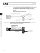
(3) Bus terminal processing
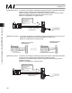
If the connector is to be connected to the network terminal node, connect the terminal resistor to the
PROFIBUS-DP communication connector as shown below or use a connector with terminal resistor.
z Example of connector with terminal resistor: SUBCON-PLUS-PROFIB/AX/SC (Phoenix Contact)
z Connecting the terminal resistor
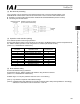
(4) Operation mode selection (setting)
Set a desired operation mode using a parameter.
Set the mode selector switch on the front side of the controller to the MANU position, and then set parameter No.
84, “FMOD: Fieldbus operation mode” using the RC PC software (V8.00.00.00 or later).
(Refer to 5.7, “PROFIBUS-DP Parameters.”)
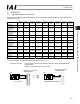
Set value Operation mode
Number of
occupied bytes
0 (factory setting) Remote I/O mode 2
1 Position/simple direct mode 8
2 Half direct mode 16
3 Full direct mode 32
4 Remote I/O mode 2 12
5 Position/simple direct mode 2 8
6 Half direct mode 3 16
7 Remote I/O mode 3 12
8 Half direct mode 3 16
* If a greater value is entered, an excessive input error will occur.
(5) Node address setting
Set the node address using a parameter.
Set parameter No. 85, “NADR: Fieldbus node address” using the RC PC software.
(Refer to 5.7, “PROFIBUS-DP Parameters.”)
Settable range: 0 to 125 (The parameter has been set to 1 at the factory.)
(Note 1) Pay attention to duplicate node address settings.
(Note 2) PROFIBUS-DP node addresses are set with the master station always having address 0. Accordingly,
addresses of slave stations can be set between 1 and 125.
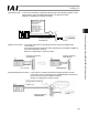
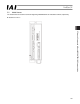
Board-end female
connector
Network-end male connector
(from counter-insertion side)
Network
wiring