
Manual


3. SCON-CA/CFA
75
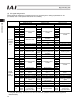
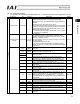
Setting of parameter No. 25
512-point mode Solenoid valve mode 1 Solenoid valve mode 2
3 4 5
Category Port No. Symbol Signal name Symbol Signal name Symbol Signal name
0 PC1 ST0 Start position 0 ST0 Start position 0
1 PC2 ST1 Start position 1 ST1 Start position 1
2 PC4 ST2 Start position 2 ST2 Start position 2
3 PC8 ST3 Start position 3 -
4 PC16 ST4 Start position 4 -
5 PC32 ST5 Start position 5 -
6 PC64 ST6 Start position 6 -
7 PC128 - -
8 PC256
Command position
number
-
Cannot be used.
-
Cannot be used.
9 BKRL Forced brake release BKRL Forced brake release BKRL Forced brake release
10 RMOD Operation mode RMOD Operation mode RMOD Operation mode
11 HOME Home return HOME Home return -
12 *STP Pause *STP Pause -
13 CSTR Positioning start - Cannot be used. -
Cannot be used.
14 RES Reset RES Reset RES Reset
PLC output
o PCON
-CA/CFA
input
15 SON Servo ON command SON Servo ON command SON Servo ON command
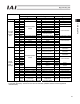
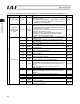
0 PM1 PE0 Completed position 0 LS0
Rear end move
command 0
1 PM2 PE1 Completed position 1 LS1
Rear end move
command 1
2 PM4 PE2 Completed position 2 LS2
Rear end move
command 2
3 PM8 PE3 Completed position 3 -
4 PM16 PE4 Completed position 4 -
5 PM32 PE5 Completed position 5 -
6 PM64 PE6 Completed position 6 -
Cannot be used.
7 PM128 ZONE1 Zone 1 ZONE1 Zone 1
8 PM256
Completed position
number
PZONE/
ZONE2
Position zone/
Zone 2
PZONE/
ZONE2
Position zone/
Zone 2
9 RMDS Operation mode RMDS Operation mode RMDS Operation mode
10 HEND Home return complete HEND Home return complete HEND Home return complete
11 PEND Positioning complete PEND Positioning complete - Cannot be used.
12 SV Operation ready SV Operation ready SV Operation ready
13 *EMGS Emergency stop *EMGS Emergency stop *EMGS Emergency stop
14 *ALM Alarm *ALM Alarm *ALM Alarm
PCON
-CA/CFA
output o
PLC input
15
LOAD/
TRQS/
*ALML
Load output judgment/
Torque level/
Light error status
LOAD/
TRQS/
*ALML
Load output judgment/
Torque level/
Light error status
*ALML
Light error status
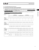
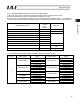
* Indicates a signal that is normally ON.
The signals denoted by “Cannot be used” are not controlled. (ON/OFF statuses of these signals are
indeterminable.)