
Manual

14
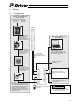
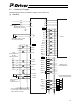
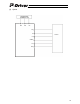
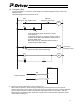
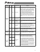
4.2 Connection Diagram
The following figure shows a connection diagram of the P-Driver unit.
(1) Standard
≪
≪
≪
≪
≪
≪
≪
≪
≪
≪
≪
≪
≪
≪
≪
≪
≪
≪
≪
≪
≪
≪
≪
≪
≪
≪
≪
≪
≪
≪
≪
≪
≪
≫
≫
≫
≫
≫
≫
≫
≫
≫
≫
≫
≫
≫
≫
≫
≫
≫
゛
゛
゛
゛
゛
MS
L
N
PE
+
-
BK
PIO
17 PP
18/PP
15 NP
16/NP
9 SON
10 RES
11 ORGC
12 TL
13 CSTP
14 COM-B
2 COM-A
1 COM-A
U
PE
V
W
ENC
A 1
/
A 2
B 3
/
B 4
Z 5
/
Z 6
SD 7
/
SD 8
BAT 9
VCC 11
GND 12
BKP 14
BKN 13
FG 15
/
BAT 10
PIO
BFB 21
/
BFB 22
ZFB 23
/
ZFB 24
/
AFB 20
GND 25
GND 26
AFB 19
RUN 4
INP 5
ORGR 6
TLR 7
ALM 8
SRDY 3
0 VDC
(NPN specification)
24 VDC
(PNP specification)
24 VDC
0 VDC
Power supply:
Single-phase, 100 VAC
Single-phase, 200 VAC
Brake power supply: 24 VDC
(for actuator with brake)
Power supply for
I/O signal
interface: 24 VDC
Connect the PIO shielded cable to the
connector shell. An optional external I/O
cable is already connected.
A
ctuato
r
Feedback pulse
output (differential)
(NPN specification)
(PNP specification)
Load
Load
Load
Load
Load
Load