
Manual

20
Signal
classificati
on
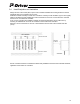
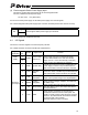
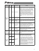
Pin
No.
Symbol Signal name Function
19 AFB +A
20 /AFB -A
21 BFB +B
22 /BFB -B
23 ZFB +Z
24 /ZFB -Z
Outputs position detection data as a pulse train
(differential).
The output pulse mode can be chosen from
90-degree phase shifted signal (phases A/B, in
quadrature), pulse train + forward/reverse signal,
and forward/reverse pulse, and output logic mode
can be selected from positive logic and negative
logic for each of the above. (The output pulse
mode is specified using parameters.)
The resolution is determined by the electric gear
ratio of the command pulse input. (The position
detection data is output with the same resolution
as the command signal.)
25
Feedback
pulse output
(differential)
26
GND
Reference
potential
Line driver ground line for feedback pulse output
(Pins 25 and 26 are internally connected.)
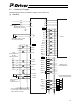
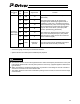
* Connectors (plugs and shells) are standard accessories.
* Optional external I/O cables (CB-PD-PIOS020) are prepared.
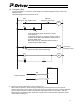
z Note that the actuator moves in the negative direction with a forward pulse (forward for the motor) and
in the positive direction with a reverse pulse (reverse for the motor). (Opposite applies to folded motor
type actuators.)
z When considering the forward/reverse direction, pay attention to the settings of the host controller or
connection of PP and /PP as well as NP and /NP.
* The rotation direction of the motor is indicated by setting CCW to forward, as seen from the axis edge
of the load side.
Caution