
Manual

42
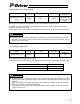
b. Do not enter a value less than the encoder’s resolution for the minimum movement unit.
)(pulse/rev pulses encoder of Number
(mm/rev) length leadscrew Ball
(mm/pulse) resolution encoder axis Linear =
)(pulse/rev pulses encoder of Number
rate reduction gear axis Rotational x (deg/rev) 360
)(deg/pulse resolution encoder axis Rotational =
The actuator will not move until the sum of command pulses sent to P-Driver has accumulated to the level
of the encoder’s resolution or more.
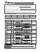
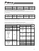
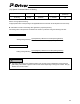
(2) Command Pulse Input Mode
Name Symbol Unit Input range
Default value
(reference)
Command pulse
input mode
CPMD (HEX input) 00~12h 01h
Set the pulse train input mode of the command pulse inputs (PP, /PP, NP and /NP).
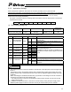
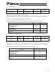
Command pulse-train
mode
Symbol Forward Reverse Setting value
Forward
pulse train
PP /PP
Reverse
pulse train
NP /NP
12h
A forward pulse train indicates motor revolutions in the forward direction, while a reverse pulse train indicates motor
revolutions in the reverse direction.
Pulse train PP /PP
Sign NP /NP
Low
High
11h
A command pulse indicates motor revolutions and its sign indicates the rotating direction of the motor.
PP /PP
Phase A/B
pulse train
NP /NP
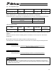
10h
Negative logic
Motor revolutions and rotating direction are specified by phases A/B (4 multiplications) with a 90-degree phase difference.
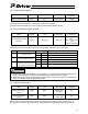
Forward
pulse train
PP /PP
Reverse
pulse train
NP /NP
02h
Pulse train PP /PP
Sign NP /NP
High
Low
01h
PP /PP
Positive logic
Phase A/B
pulse train
NP /NP
00h
Make the same positive/negative logic setting as for FBPT regardless of whether the feedback pulse
(FBPT) is used or not. See (27), “FBP Mode,” for the explanation about FBPT.
Caution