
Manual

43
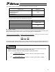
6.3.2 Application Settings
Set the parameters explained in this section as necessary according to the system and load.
Default values indicated by [A] have already been set to appropriate values corresponding to the applicable
actuator at shipment from the factory. They normally do not require changing.
Some of the parameters must be input as binary values (indicated as bit input in the unit column).
[Data structure of bit-input parameters]
The layout of numerical values for a setting value is as follows. Follow the layout below to set each bit
explained in this manual.
Bit No. 7 6 5 4 3 2 1 0
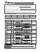
(1) PIO Function Setting Flag
Name Symbol Unit Input range
Default value
(reference)
PIO function setting flag FPIO (Bit input) 0000000~1111111b 0b
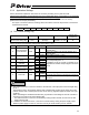
Set the functions of I/O signals by setting each of the 7 bits to 1 or 0.
Bit No. Signal name Symbol Setting Status
0 +
The motor rotates in the forward direction by a
forward pulse
6
Command pulse
count direction
CPR
1 -
The motor rotates in the reverse direction by a
reverse pulse.
0 Enabled The feedback pulse is output.
5 Feedback pulse FBP
1 Disabled The feedback pulse is not output.
0 Enabled
4
External forced
stop
CSTP
1 Disabled
0 Enabled
3
Torque limit
selection
TL
1 Disabled
0 Enabled
2
Homing
command signal
ORGC
1 Disabled
0 Enabled
1 Alarm reset RES
1 Disabled
It is possible to disable a given signal by setting
the corresponding bit to “1.”
If “Disabled” is set for a signal, it is treated as “off”
regardless of whether the input signal is turned on
or off.
0 Enabled
With this input signal turned on, the servo is
turned off when the servo ON signal is turned off.
0 Servo ON SON
1 Disabled
The servo is turned on when the power supply is
turned on.
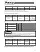
a. The revolution direction of the motor relative to the direction of the input pulse can be changed using
bit No. 6.
The actuator moves in the negative direction with a forward pulse (forward for the motor) and in the
positive direction with a reverse pulse (reverse for the motor). (Opposite applies to folded motor type
actuators).
When considering the forward/reverse direction, pay attention to the settings of the host controller or
connection of PP and /PP as well as NP and /NP.
* The rotation direction of the motor is indicated by setting CCW to forward, as seen from the axis
edge of the load side.
b. If “Disabled” is selected for bit No. 0, the servo is turned on/off by turning the power supply on/off.
While the power supply is turned on, the servo can only be turned on/off by the PC software.
Caution