PS241 / PS242 24V Power Supply Instruction Manual Second Edition
Please Read Before Use Thank you for purchasing our product. This Instruction Manual describes all necessary information to operate this product safely such as the operation procedure, structure and maintenance procedure. Before operation, read this manual carefully and fully understand it to operate this product safely. The enclosed CD in this product package includes the Instruction Manual for this product.
Table of Contents Safety Guide......................................................................................................... 1 Precautions in Handling....................................................................................... 7 1. Name and Function of Each Part................................................................... 9 2. RDY Display and RDY Output Signal........................................................... 11 3. Product Check...........................................
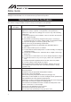
Safety Guide "Safety Guide" has been written to use the machine safely and so prevent personal injury or property damage beforehand. Make sure to read it before the operation of this product. Safety Precautions for Our Products The common safety precautions for the use of any of our robots in each operation. No.
No. Operation Description Precautions 3 Storage and Preservation ● The storage and preservation environment conforms to the installation environment. However, especially give consideration to the prevention of condensation. 4 Installation and Start (1) Installation of Robot Main Body and Controller, etc. ● Make sure to securely hold and fix the product (including the work). A fall, drop or abnormal motion of the product may cause damage or injury. ● Do not get on or put anything on the product.
No. Operation Description Precautions 4 Installation and Start (4) Safety Measures ● When the product is under operation or in the ready mode, take the safety measures (such as the installation of safety and protection fence) so that nobody can enter the area within the robot’s movable range. When the robot under operation is touched, it may result in death or serious injury.
No. Operation Description Precautions 6 Trial Operation ● After the teaching or programming operation, perform the check operation one step by one step and then shift to the automatic operation. ● When the check operation is to be performed inside the safety protection fence, perform the check operation using the previously specified work procedure like the teaching operation. ● Make sure to perform the programmed operation check at the safety speed.
No. Operation Description Precautions 9 Modification ● Do not modify, disassemble, assemble or use of maintenance parts not specified based at your own discretion. ● In such case, the warranty is not applied. 10 Disposal ● When the product becomes no longer usable or necessary, dispose of it properly as an industrial waste. ● Do not put the product in a fire when disposing of it. The product may burst or generate toxic gases.
Alert Indication The safety precautions are divided into “Danger”-“Warning”-“Caution”-“Notice” according to the warning level, as follows, and described in the Instruction Manual for each model. Level Degree of Danger and Damage Symbol Danger This indicates an imminently hazardous situation which, if the product is not handled correctly, will result in death or serious injury.
Precautions in Handling PS-24 Power Supply is a power supply unit dedicated for IAI controllers which utilizes 24V DC as a power source. There are 2 types, 100V AC and 200V AC specifications, for the input power. Even when lack of the power capacity is occurred, this power supply does not need to be replaced with another power supply with a bigger capacity. Another unit of this product can be added to the connection to perform a parallel operation. 5 units maximum can be connected.
1. Name and Function of Each Part 1) 2) 3) 4) 5) 6) 7) 8) 9) 10) 11) 1) RDY display It is illuminated in normal operation. [Refer to "2. RDY Display and RDY Output Signal".] 2) Variable dial to set over load detection level For manufacturer’s use only. Do not remove the seal. 3) RDY output signal It turns ON (electrically conducted) in normal operation. [Refer to "2. RDY Display and RDY Output Signal".] 4) 5) +24V output terminal * 4) and 5) are connected internally.
10) AC input terminal (for 100V AC) Input terminal for 100V AC type. Note : Do not connect the unit to a power source that is not specified. 11) AC input terminal (for 200V AC) Input terminal for 200V AC type. Note : Do not connect the unit to a power source that is not specified. (Note) Connect the power supply as follows; for 100V AC input specification, 9) and 10), and for 200V AC input specification, 9) and 11). They cannot be used in common for each specification.
2. RDY Display and RDY Output Signal In a normal operation, RDY display should be illuminated and RDY output signal should be turned ON (electrically conducted). In case this RDY display is not illuminated and RDY output signal is turned OFF, lower the load or add another unit of this power supply. Take note that there are also other considerable causes that the RDY display light and RDY output signal are OFF as listed below.
3. Product Check This product is comprised of the following parts if it is of standard configuration. If you find any fault in the contained model or any missing parts, contact us or our distributor. 3.1 Parts (The option is excluded.) No. 1 Part Name Model 24V Power Supply Main Unit Refer to “How to read the model plate”, “How to read the model No.” Accessories 3.
4. Basic Specifications Specifications Specification Item 200V AC Specification PS242 100V AC Specification PS241 Rated Voltage DC Output 24V±10% (fluctuates depending on duty) Rated DC Current Output 8.5A Peak Maximum DC Current 17A Output Rated Output Wattage 204W Efficiency 80% Rated Input Voltage (frequency) 100 to 115V AC (50/60Hz) 200 to 230V AC (50/60Hz) Input Voltage Range 90 to 125V AC 180 to 250V AC Input Current 3.5A 1.
External Dimensions 64.5 31.5 33 24V 24V 0V 0V FG AC(N) AC100(L) AC200(L) 5 10 138 10 5 φ5 (For installation) 158 148p0.5 31.5 5 33 R2.5 (For installation) 139.5 13 8 M3.5 Terminal screw 10 5.
6. Installation Environment Do not use this product in the following environment.
7. Installation and Noise Elimination 1. Grounding Power Supply +24V +24V 0V 0V FG AC(N) AC100(L) AC200(L) Class D grounding (Formerly Class- III grounding: Grounding resistance at 1007 or less) Power Supply Other equipment Other equipment Other equipment Do not share the ground wire with or connect to other equipment. Ground each controller. 20mm or more 100mm or more 50mm or more 20mm or more 50mm or more 2. Heatsink and Mounting Method This is a natural air-cooling type power supply.
Both methods A (standard) and B below are available as a mounting method, however, the characteristics for the output current relevant to the temperature will differ for each way. Use within the range of its characteristics for each method. Mounting Surface Output Current (%) Method A (Standard) Method B 110 100 90 80 70 60 50 40 30 20 10 0 A (Standard) B 0 10 20 30 40 50 60 Ambient Temp.
8. Output Voltage This power supply is able to be used in a parallel operation, and the output voltage fluctuates within the range of 24V±10% even in a normal operation. The voltage is set to around 25.8V at no duty. This voltage fluctuation does not influence the operation of IAI 24V controller at all. This power supply changes the voltage within the area between the solid line and the broken line below in response to the load. Output Voltage Fluctuation in accordance with Duty 26.
9. Protective Functions There are 4 patterns of circuits prepared as a protection function. (1) Over Current Protection Circuit The voltage suddenly drops when the current more than the rated value is output (includes short circuit). Power output automatically recovers when the over current condition is cancelled. There is a case that the over current protection circuit works due to the in-rush current caused by turning ON multiple controllers at the same time.
10. Parallel Operation Parallel operation is available under the following conditions. Parallel operation is allowed up to 5 units. Do not connect a different type power supply unit from PS-24 Power Supply in parallel. 2 terminals for each of positive side and negative side as the output terminals are provided. Use one terminal for the parallel connection, and the other for the connection to the load.
11. Simple Troubleshooting Contents Voltage does not output. Output voltage is low. RDY display does not illuminate. 21 Treatment Is the connected input voltage within the specification? Any short circuit or grounding fault on the output circuit? Time delay too short after over voltage or over temp protection activated.
Appendix 1 Power Supply Unit PS241/PS242 and Number of Connectable Controllers Table:1 Relation of Actuator and Power Supply Current Controller Type Actuator Type Motor Power Capacity SA4, SA5, RA4 (20W) type RCA SA6, RA4 (30W) type RA3 (20W) type SA3 (10W) type SA5, TA6 (20W) type ACON ASEL ASEP RCA2 RN3N, RP3N, GS3N, GD3N, SA3N TC3N, TW3N, TF3N, TA4C, TA4R (10W) type SA6, TA7 (30W) type RA4, TA5 (20W) type RN4N, RP4N, GS4N, GD4N SD4N, TC4N, TW4N, TF4N (20W) type RA1L, SA1L (2W) type RCL RA2L, SA2
Number of Power Supply Units Table:2 Power Supply Rated Current and Allowable Peak Maximum Current No. of Connectable Units Rated Current [A] Peak Maximum Current [A] 1 unit 8.5 17 2 units 15.3 30.6 3 units 22.95 45.9 4 units 30.6 61.2 5 units 38.25 76.5 * For the 2nd unit or more, 10% safety factor (loss) is considered.
Appendix 2 Determination for Number of Connectable Units Referring to Tables 1 and 2, determine the number of units to connect considering that the rated current of load is within the rated current value of the power supply. There is the RDY display to detect the duty ratio on the power supply. Also, this product is available for parallel operation.
How to Calculate Power Supply Capacity Rated current of each actuator [A] × Number of actuators < Rated current per power supply unit [8.5A] Max. current of each actuator [A] × Number of actuators to operate at one time < Transient max.
Warranty Period and Scope of Warranty The controller you have purchased has passed IAI’s shipping inspection implemented under the strictest standards. The product is covered by the following warranty: 1. Warranty Period The warranty period expires upon elapse of one of the following periods, whichever is the shortest. 18 months after shipment from IAI. 12 months after delivery to the specifi ed location. 2.
Change History Revision Date Revision Description 2008.02 First Edition 2010.
Manual No.: ME0129-2A (December 2010) Head Office: 577-1 Obane Shimizu-KU Shizuoka City Shizuoka 424-0103, Japan TEL +81-54-364-5105 FAX +81-54-364-2589 website: www.iai-robot.co.