ROBO Cylinder RCA2 Actuator Table Type Operating Manual Ninth Edition Motor coupling types [Slim Small ROBO Cylinder] TA4C TA5C, TA6C, TA7C Motor unit types [Slim Small ROBO Cylinder] TA4R Motor reversing types TA5R, TA6R, TA7R Compact types [Slim Small ROBO Cylinders] Wide types Short types Flat types TCA3NA, TCA4NA, TCA3N, TCA4N TWA3NA, TWA4NA, TWA3N, TWA4N TFA3NA, TFA4NA, TFA3N, TFA4N IAI America, Inc.
Please Read Before Use Thank you for purchasing our product. This Operating Manual describes all necessary information to operate this product safely such as the operation procedure, structure and maintenance procedure. Before operation, read this manual carefully and fully understand it to operate this product safely. The enclosed CD/DVD in this product package includes the Operating Manual for this product.
CE Marking If a compliance with the CE Marking is required, please follow Overseas Standards Compliance Manual (ME0287) that is provided separately.
Table of Contents Safety Guide ........................................................................................................................1 Handling Precautions ..........................................................................................................8 1. Part Names.................................................................................................................. 11 1.1 1.2 Motor Unit Types ........................................................................
3. Cable Drawings ...........................................................................................................34 3.1 3.2 ASEP Controller Cables..............................................................................................................34 ACON, ASEL Controller Cables .................................................................................................35 4. Options....................................................................................................
11.2 11.3 11.4 Adjusting the Home Position.......................................................................................................92 Changing the Home Position Direction ......................................................................................92 How to Move Table by Hand.......................................................................................................93 12. Life ................................................................................................
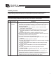
Safety Guide “Safety Guide” has been written to use the machine safely and so prevent personal injury or property damage beforehand. Make sure to read it before the operation of this product. Safety Precautions for Our Products The common safety precautions for the use of any of our robots in each operation. No.
No. 2 2 Operation Description Transportation 3 Storage and Preservation 4 Installation and Start Description When carrying a heavy object, do the work with two or more persons or utilize equipment such as crane. When the work is carried out with 2 or more persons, make it clear who is to be the leader and who to be the follower(s) and communicate well with each other to ensure the safety of the workers.
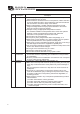
No. 4 Operation Description Installation and Start Description (2) Cable Wiring Use our company’s genuine cables for connecting between the actuator and controller, and for the teaching tool. Do not scratch on the cable. Do not bend it forcibly. Do not pull it. Do not coil it around. Do not insert it. Do not put any heavy thing on it. Failure to do so may cause a fire, electric shock or malfunction due to leakage or continuity error.
No. 4 5 4 Operation Description Installation and Start Teaching Description (4) Safety Measures When the work is carried out with 2 or more persons, make it clear who is to be the leader and who to be the follower(s) and communicate well with each other to ensure the safety of the workers. When the product is under operation or in the ready mode, take the safety measures (such as the installation of safety and protection fence) so that nobody can enter the area within the robot’s movable range.
No. 6 7 Operation Description Trial Operation Automatic Operation Description When the work is carried out with 2 or more persons, make it clear who is to be the leader and who to be the follower(s) and communicate well with each other to ensure the safety of the workers. After the teaching or programming operation, perform the check operation one step by one step and then shift to the automatic operation.
No. 8 9 6 Operation Description Maintenance and Inspection 10 Modification and Dismantle Disposal 11 Other Description When the work is carried out with 2 or more persons, make it clear who is to be the leader and who to be the follower(s) and communicate well with each other to ensure the safety of the workers. Perform the work out of the safety protection fence, if possible.
Alert Indication The safety precautions are divided into “Danger”, “Warning”, “Caution” and “Notice” according to the warning level, as follows, and described in the Operation Manual for each model. Level Degree of Danger and Damage Symbol This indicates an imminently hazardous situation which, if the Danger product is not handled correctly, will result in death or serious injury.
Handling Precautions 1. Do Not Set Speed and Acceleration/Deceleration Higher Than the Rated Values. Do not set speed and acceleration/deceleration higher than the rated values. It causes vibration, failure, or shortening of life. If acceleration/deceleration higher than the rated value is set, creeping phenomenon or coupling slide may occur. 2. The Allowable Load Moment Must be Within the Tolerance. The allowable load moment must be within the tolerance value.
6. Transportation 6.1 Handling a Single Actuator Please adhere to the following when handling a single actuator. 6.1.1 Handling the Packed Unit Unless otherwise specified, the actuator is shipped with each axis packaged separately. Do not damage or drop. The package is not applied with any special treatment that enables it to resist an impact caused by a drop or crash. Transport a heavy package with at least more than two operators. Consider an appropriate method for transportation.
6.2 Handling the Actuator Assembly When carrying the actuator, exercise caution not to bump it against nearby objects or structures. Secure the sliders to prevent sudden movement during transport. If any end of the actuator is overhanging, secure it properly to avoid significant movement due to external vibration. When transporting the assembly without the ends of the actuators fastened, do not subject the assembly to an impact of 0.3 G or more.
1. Part Names 1. Part Names The names of the actuator parts are indicated below. In this manual, the right and left are determined by viewing the actuator from the top and from the motor side. Also, the front side means the side opposite from the motor. 1.1 Motor Unit Types 1.1.1 Motor coupling types RCA2-TA4C, TA5C, TA6C, TA7C Ball screw cover Right Motor side Other side Front plate * * Left Table Motor unit Connector Refer to 2, “External Dimensions” for details.
1.2 Short Types 1. Part Names 1.2.1 Compact types RCA2-TCA3NA, TCA3N (Slide screw, Ball screw), TCA4NA,TCA4N (Slide screw, Ball screw) Connector Cover Table Right Side Front Rear Left Side Cable Front Plate Main Body (Aluminum Frame) * Refer to 2, “External Dimensions” for details. 1.2.
1.2.3 1. Part Names Flat types RCA2-TFA3NA, TFA3N (Slide screw, Ball screw), TFA4NA, TFA4N (Slide screw, Ball screw) Connector Cover Table Right Side Front Rear Left Side Cable Front Plate Main Body (Aluminum Frame) * Refer to 2, “External Dimensions” for details.
90 115 37 40 29 13 5 48 SE 18 25 12 8 16 J-M4, depth 7.5 4H7, depth 4.5 (from bottom face of base) ME 3 ST 4H7, depth 4.5 (from top face of table) (Side view of motor unit when cable exit direction is changed (option)) 29 20 31 Depth 6 3-M5, depth 7 5 5 E× 50 50 20 30 40 50 60 70 80 90 100 ST (Reamed hole/ long hole pitch) 40 (Reamed hole/ long hole pitch) G×40 B 5 A Without brake 214.5 224.5 234.5 244.5 254.5 264.5 274.5 284.5 294.5 5 D 4H7, deapth 4.
25 50 75 100 ST Without brake 244 269 294 319 L 284.5 309.5 334.5 359.5 With brake 103 128 153 178 A 113 138 163 188 B 135.5 160.5 185.5 210.5 C 103 128 153 178 D 1 1 2 2 E 43 68 43 68 F 1 1 2 2 G 4 4 6 6 H Detail view of T-groove (2:1) Brake type 6 6 8 8 J Weight [kg] Without With brake brake 1.2 1.5 1.4 1.7 1.5 1.8 1.7 2.0 J-M5, depth 10 φ5H7, depth 5 φ5H7, depth 5 92.5 117.
25 50 75 100 125 150 ST Without brake 244.5 269.5 194.5 319.5 344.5 369.5 L 284 3.9 334 359 384 409 With brake 108 133 158 183 208 233 A 121 146 171 196 221 246 B 147.5 172.5 197.5 222.5 247.5 272.5 C 110.5 135.5 160.5 185.5 210.5 235.5 D 1 1 2 2 3 3 E 50.5 75.5 50.5 75.5 50.5 75.5 F 1 1 2 2 3 3 G 4 4 6 6 8 8 H 6 6 8 8 10 10 J Detail view of T-groove (2:1) Brake type 3-M6, depth 13 1.8 2.0 2.2 2.4 2.6 2.8 2.2 2.4 2.6 2.8 3.0 3.
50 75 100 125 150 175 200 ST Without brake 261.5 286.5 311.5 336.5 361.5 386.5 411.5 436.5 L 301 328 351 376 401 426 451 476 With brake 118 143 168 193 218 243 268 293 A 133 158 183 208 233 258 283 308 B 149.5 174.5 199.5 224.5 249.5 274.5 299.5 324.5 C 110.5 135.5 160.5 185.5 210.5 235.5 260.5 285.5 D 1 1 2 2 3 3 4 4 E 50.5 75.5 50.5 75.5 50.5 75.5 50.5 75.
5 5 13 29 90 115 37 40 29 81 3.1 18 25 37.9 3 SE ST 16 J-M4, depth 7.5 12 8 5 Ensure 100 or more H-M4, depth 6 φ4H7, depth 4.5 (from bottom face of base) ME φ4H7, depth 4.5 (from top face of table) (Side view of motor unit when cable exit direction is changed (option)) 48 3-M5, depth 6 Brake type 37.5 11 37 32 20 31 18 L 129 139 149 159 169 179 189 199 209 20 30 40 50 60 70 80 90 100 B 5 ST E× 50 (Reamed hole/ long hole pitch) 50 40 G×40 A 5 D 4H7, depth 4.
18 25 151 176 201 226 25 50 75 100 103 128 153 178 A 113 138 163 188 B 103 128 153 178 D 1 1 2 2 E 43 68 43 68 F 1 1 2 2 G 4 4 6 6 H (With brake) (*) On ST-25 models brake types, the motor unit projects from the tip of the table (at the home position). L ST 3-M6, depth 10 Brake type 6 6 8 8 J (Side view of motor unit when cable exit direction is changed (option)) 92.5 50 32 1.4 1.6 1.7 1.9 1.7 1.9 2.0 2.
20 161.5 186.5 211.5 236.5 261.5 286.5 25 50 75 100 125 150 108 133 158 183 208 233 A 121 146 171 196 221 246 B 110.5 135.5 160.5 185.5 210.5 235.5 D 1 1 2 2 3 3 E 50.5 75.5 50.5 75.5 50.5 75.5 F 3-M6, depth 13 Brake type 1 1 2 2 3 3 G (*) On ST-25 models brake types, the motor unit projects from the tip of the table (at the home position). L ST 121 18 25 4 4 6 6 8 8 H 6 6 8 8 10 10 J (With brake) 32 57 Weight [kg] Without With brake brake 2.1 2.5 2.3 2.7 2.5 2.9 2.7 3.1 2.9 3.
163.5 188.5 213.5 238.5 263.5 288.5 313.5 338.5 25 50 75 100 125 150 175 200 39.5 118 143 168 193 218 243 268 293 A 133 158 183 208 233 258 283 308 B 5 66 110.5 135.5 160.5 185.5 210.5 235.5 260.5 285.5 D 1 1 2 2 3 3 4 4 E 75 73 44 50.5 75.5 50.5 75.5 50.5 75.5 50.5 75.5 F 138.5 G (5) 1 1 2 2 3 3 4 4 A 4 4 6 6 8 8 10 10 H 58.5 179.2 (With brake) Brake type (*) On ST-25 models brake type, the motor unit projects from the tip of the table (at the home position). L ST 6.
31 7 16 4 Connector Cable exit direction: K2 4-M4, through 32 3 +0.050 0 depth 3 depth 3 F3+0.030 0 22.6 23 16 6 Home 30 4-M4, depth 4 8 2 8 ME 26 26 10 46 4 25 30 3 Ensure 100 or more 2-M3, depth 3 4-M4, depth 5.5 3 depth F3+0.030 0 depth 3 F3+0.050 0 73.5 40 86.5 89.5 depth 3 F3 +0.050 0 40 +0.030 depth 0 F3 7 20 19 5.5 10.5 B A L 89.5 86.5 73.5 109.5 106.5 93.5 4 Weight [kg] 0.37 0.
10.5 depth 3 F3+0.030 0 23 7 36 20 3 +0.050 0 depth 3 4 34 24 20 4-M4, through 51 49 7 10 8 28 48 28 10 depth 3 F3+0.030 0 4-M4, depth 5 2 Home ME 30 22 21 6.5 4 25 30 40 98 95 40 80 3+0.050 depth 3 0 3+0.050 depth 3 0 2-M3, depth 4 Ensure 100 or more 7 depth 3 F3+0.030 0 4 L 98 118 A 95 115 B 80 100 4 Weight [kg] 0.48 0.60 Equipped with Gauge Slippage Protection Function (Note) Only 30mm is available for the stroke of Slide Screw TCA4N Type.
depth 3 F3+0.030 0 29 12 26 50 4 3+0.050 0 depth 3 Connector Cable exit direction: K2 4-M4, through 21 16 6.5 Home 30 37 37 8 10 46 depth 3 F3+0.030 0 4-M4, depth 6 8 ME 2 26 4 25 30 73.5 3+0.050 depth 3 0 3+0.050 depth 3 0 89.5 86.5 40 ST 30 50 9 5 10.5 B A L 89.5 86.5 73.5 109.5 106.5 93.5 40 Weight [kg] 0.52 0.58 Equipped with Gauge Slippage Protection Function (Note) Only 30mm is available for the stroke of Slide Screw TWA3N Type.
depth 3 F3+0.030 0 10.5 23 14 58 30 4 31 21 20 4-M4, through 46 48 3+0.050 0 depth 3 6.5 10 8 10 25 depth 3 F3+0.030 0 4-M4, depth 8 30 Home ME 2 48 28 4-M4, depth 7 4 4 45 45 6.5 30 98 95 40 80 3 +0.050 depth 3 0 Ensure 100 or more 3 +0.050 depth 3 0 L 98 118 A 95 115 B 80 100 Weight [kg] 0.65 0.77 4 Equipped with Gauge Slippage Protection Function (Note) Only 30mm is available for the stroke of Slide Screw TWA4N Type.
1.5 28 57 61 24 15.5 Connector Cable exit direction: K2 2-M4, through 35 20 Home 30 50 2 8 10 4 25 depth 3 F3+0.030 0 8 26 ME 46 30 89.5 86.5 40 40 2-M3, depth 3 Ensure 100 or more 4-M4, depth 5.5 depth 3 F3+0.030 0 3 +0.050 depth 3 4-M4, depth 4 0 73.5 3 +0.050 depth 3 0 7 26 ST 30 50 3 10.5 B A L 89.5 86.5 73.5 109.5 106.5 93.5 23 Weight [kg] 0.40 0.48 Equipped with Gauge Slippage Protection Function (Note) Only 30mm is available for the stroke of Slide Screw TFA3N Type.
23 1.5 34 10.5 17 39 71 28 30.5 2-M4, through 35.5 18.5 42 10 8 28 10 depth 3 F3+0.030 0 4-M4, depth 5 ME Home 2 30 48 28 25 30 98 95 40 40 3 +0.050 depth 3 0 80 Ensure 100 or more 2-M3, depth 4 3 +0.050 depth 3 0 7 22 58 6.5 4 4 L 98 118 A 95 115 26 B 80 100 Weight [kg] 0.60 0.72 4 Equipped with Gauge Slippage Protection Function (Note) Only 30mm is available for the stroke of Slide Screw TFA4N Type.
28 3 0 + 0.030 depth 3 4-M4, through 3 0 + 0.030 depth 3 4-M4, depth 4 ME Home 4-M4, depth 5.5 + 0.030 3 0 depth 3 + 0.050 3 0 73.5 depth 3 depth 3 2-M3, depth 3 + 0.050 3 0 Ensure 100mm or more Weight [kg] 0.37 ST 30 2-M4, depth 6 [Option] Cable Exit Direction Changed 2. External Dimensions 2.15 RCA2-TC3N (Slide screw) Ball Guide Type (Option: Model Code BG) 3 0 depth 3 +0.
3 0 + 0.030 depth 3 4-M4, through 3 0 depth 3 +0.050 ME Home + 0.030 3 0 + 0.030 depth 3 4-M4, depth 5 33 4-M4, depth 6 Ensure 100 or more depth 3 depth 3 + 0.050 3 0 + 0.050 3 0 2-M3, depth 4 depth 3 Weight [kg] 0.48 ST 30 2-M4, depth 8 [Option] Cable Exit Direction Changed 2. External Dimensions 3 0 2.
30 3 0 + 0.030 depth 3 4-M4, through depth 3 + 0.030 3 0 depth 3 4-M4, depth 6 ME Home 4-M4, depth 8 + 0.030 3 0 + 0.050 3 0 Ensure 100 or more depth 3 depth 3 + 0.050 3 0 Weight [kg] 0.52 ST 30 3-M4, depth 6 [Option] Cable Exit Direction Changed 2. External Dimensions 2.17 RCA2-TW3N (Slide screw) Ball Guide Type (Option: Model Code BG) 3 0 depth 3 +0.
3 0 + 0.030 depth 3 4-M4, through 3 0 depth 3 +0.050 4-M4, depth 8 ME depth 3 4-M4, depth 8 + 0.030 3 0 depth 3 Home + 0.030 + 0.050 3 0 Ensure 100 or more depth 3 depth 3 + 0.050 3 0 Weight [kg] 0.65 ST 30 4-M4, depth 8 [Option] Cable Exit Direction Changed 2. External Dimensions 3 0 2.
32 2-M4, through depth 3 + 0.030 3 0 depth 3 4-M4, depth 4 ME Home 4-M4, depth 5.5 + 0.030 3 0 2-M3, depth 3 + 0.050 3 0 depth 3 Ensure 100 or more + 0.050 3 0 depth 3 Weight [kg] 0.4 ST 30 3-M4, depth 6 [Option] Cable Exit Direction Changed 2. External Dimensions 2.
2-M4, through depth 3 4-M4, depth 6 + 0.030 3 0 + 0.030 depth 3 4-M4, depth 5 ME Home + 0.050 3 0 2-M3, depth 4 depth 3 + 0.050 3 0 depth 3 Ensure 100 or more Weight [kg] 0.6 ST 30 [Option] Cable Exit Direction Changed 3-M4, depth 8 2. External Dimensions 3 0 2.
3. Cable Drawings 3.1 ASEP Controller Cables Motor/encoder cable (CB-APSEP-MPA***) 3. Cable Drawings *** indicates the cable length (L). Up to 10 m can be specified. Example) 080 = 8 m L (25) [1][2] [5] No. 1 2 3 4 Item [6] (30) Model number D-1100D 1-1827863-1 (black, 2.0-mm pitch, 22 poles) D-1 1827570-2 (AWG 22 to 18, 1.08 to 1.6 φ ) PADP-24V-1-S (white, 2.0-mm pitch, 24 poles) SPND-001T-C0.5 (AWG 26 to 22, 1.0 to 1.
3.2 ACON, ASEL Controller Cables RCA2 Integrated motor/encoder cable (CB-ACS-MPA***) *** indicates the cable length (L). Up to 10 m can be specified. Example) 080 = 8 m 3. Cable Drawings [1][2] [3][4] [7] Model Nameplate [7] No. [1] [2] [3] [4] [5] [6] Item Receptacle housing Receptacle contact Socket Socket contact Housing Contact Model number D-1100D 1-1827863-1 D-1 1827570-2 DF1E-3S-2.5C DF1E-2022SCF PHDR-18VR SPHD-001T-P0.
4. Options 4.1 Optional Connector Cable Exit Direction 4. Options In the standard specification, the cable exit direction is opposite to the rod and guide bracket. If it is desired to pull out the cable on the front plate side according to the device layout, etc., the cable can be pulled out from the opposite direction by using the option (model number: K2). 4.2 Power-saving Function This option reduces the maximum current of the controller compared to actuator of the standard specification.
4.5 Cable Exit Direction Changed In case of the motor unit type (TA**), the cable exit direction is changed when a change to the cable exit direction is made. There are 5 ways to change the direction, which are top side (model code: CJT), right side (model code: CJR), left side (model code: CJL), bottom side (model code: CJB) and outer side (model code: CJO).
5. Checking after Unpacking After unpacking, check the condition of the product and also check the included items. 5.1 Included Items No. 1 Item Actuator Model number Refer to “How to Read Model Nameplate” and “How to Read Model Number.” Remarks 5.
5.4 How to Read Model RCA2 - TA5C - I - 20 - 10 - 25 - A1 - P - B - ** 10 (10 W) : TA4C, TA4R, TCA3NA, TWA3NA, TFA3NA TCA3N, TWA3N, TFA3N 20 (20 W) : TCA4NA, TWA4NA TFA4NA TC4AN,TWA4N, TFA4N TA5C, TA5R, TA6C, TA6R 30 (30 W) : TA7C, TA7R *1 This may be displayed for the manufacturing reason. (This is not to indicate the manufacturing model code.
6. Specifications (1) Max. speed The maximum speed for this ROBO Cylinder is limited due to the sympathetic vibration of the ball screw shaft and the limitation of motor rotation speed. Do not exceed the maximum speed shown in the table below. Strokes and maximum speed limits (Unit: mm/s) Model name Motor type 6.
Strokes and maximum speed limits (Unit: mm/s) Model name TCA3NA (Lead screw) TCA3NA (Ball screw) TCA4NA (Lead screw) TWA3NA (Lead screw) TWA3NA (Ball screw) TWA4NA (Lead screw) TWA4NA (Ball screw) TFA3NA (Lead screw) TFA3NA (Ball screw) 10W 10W 20W 20W 10W 10W 20W 20W 10W 10W Lead [mm] Stroke [mm] 30 50 1 50 - 2 100 - 4 200 - 1 50 50 2 100 100 4 200 200 2 100 - 4 200 - 6 220 - 2 100 100 4 200 200 6 270 <220> 300 1 50 - 2 100 - 4 200 - 1 50
Strokes and maximum speed limits (Unit: mm/s) Model name TFA4NA (Lead screw) TFA4NA (Ball screw) Motor type 20W 20W Lead [mm] Stroke [mm] 30 50 2 100 - 4 200 - 6 220 - 2 100 100 4 200 200 6 270 <220> 300 (Note) Values in < > are for when mounted vertically. 6. Specifications Note : Do not set a speed or acceleration/deceleration exceeding the applicable rating. Doing so may result in vibration, failure or shorter life.
Strokes and maximum speed limits (Unit: mm/s) Model name TCA3N TC3N (Option BG) (Lead screw) TCA3N (Ball screw) TCA4N TC4N (Option BG) (Lead screw) TWA3N TW3N (Option BG) (Lead screw) TWA3N (Ball screw) TWA4N TW4N (Option BG) (Lead screw) TWA4N TW4N (Option BG) (Ball screw) 10W 10W 20W 20W 10W 10W 20W 20W Lead [mm] Stroke [mm] 30 1 50 2 100 4 200 1 50 2 100 4 200 2 100 4 200 6 220 2 100 4 200 6 270 <220> 1 50 2 100 4 200 1 50 2 100 4 200 2 100 4 200 6 220
Strokes and maximum speed limits (Unit: mm/s) Model name TFA3N TF3N (Option BG) (Lead screw) 6. Specifications TFA3N (Ball screw) TFA4N TF4N (Option BG) (Lead screw) TFA4N TF4N (Option BG) (Ball screw) Motor type 10W 10W 20W 20W Lead [mm] Stroke [mm] 30 1 50 2 100 4 200 1 50 2 100 4 200 2 100 4 200 6 220 2 100 4 200 6 270 <220> (Note) Values in < > are for when mounted vertically. Note : Do not set a speed or acceleration/deceleration exceeding the applicable rating.
(2) Acceleration and load capacity Model name Motor type Lead [mm] 2 TA4 10W 4 6 2.5 TA5 20W 5 3 TA6 20W 6 12 3 TA7 30W 6 12 Load capacity [kg] Horizontal 0.2 3 Vertical 0.2 1.5 Horizontal 0.3 2 Vertical 0.2 1 Horizontal 0.3 1 Vertical 0.2 0.5 Horizontal 0.2 5 Vertical 0.2 3 Horizontal 0.3 3.5 Vertical 0.2 2 Horizontal 0.3 2 Vertical 0.2 1 Horizontal 0.2 6 Vertical 0.2 3 Horizontal 0.3 4 Vertical 0.2 1.5 Horizontal 0.3 2 Vertical 0.2 0.
Model name Motor type Lead [mm] 1 TCA3NA TCA3N TC3N (Option BG) (Lead screw) 10W 2 4 1 6. Specifications TCA3NA TCA3N (Ball screw) 10W 2 4 2 TCA4NA TCA4N TC4N (Option BG) (Lead screw) 20W 4 6 2 TCA4NA TCA4N TC4N (Option BG) (Ball screw) 20W 4 6 1 TWA3NA TWA3N TW3N (Option BG) (Lead screw) 10W 2 4 1 TWA3NA TWA3N (Ball screw) 10W 2 4 Rated acceleration [G] Load capacity [kg] Horizontal 0.2 1 Vertical 0.2 0.5 Horizontal 0.2 0.5 Vertical 0.2 0.25 Horizontal 0.2 0.
Model name Motor type Lead [mm] 2 TWA4NA TWA4N TW4N (Option BG) (Lead screw) 20W 4 6 2 TWA4NA TWA4N TW4N (Option BG) (Ball screw) 20W 4 1 TFA3NA TFA3N TF3N (Option BG) (Lead screw) 10W 2 4 1 TFA3NA TFA3N (Ball screw) 10W 2 4 2 TFA4NA TFA4N TF4N (Option BG) (Lead screw) 20W 4 6 2 TFA4NA TFA4N TF4N (Option BG) (Ball screw) 20W 4 6 Load capacity [kg] Horizontal 0.2 1 Vertical 0.2 0.5 Horizontal 0.2 0.5 Vertical 0.2 0.25 Horizontal 0.2 0.25 Vertical 0.2 0.
(3) Rated thrust Model name TA4 TA5 6. Specifications TA6 TA7 TCA3NA TCA3N TC3N (Option BG) (Lead screw) TCA3NA TCA3N (Ball screw) TCA4NA TCA4N TC4N (Option BG) (Lead screw) TCA4NA TCA4N TC4N (Option BG) (Ball screw) TWA3NA TWA3N TW3N (Option BG) (Lead screw) TWA3NA TWA3N (Ball screw) 48 Motor type 10W 20W 20W 30W 10W 10W 20W 20W 10W 10W Lead [mm] Rated thrust [N] 2 85 4 43 6 28 2.5 137 5 68 10 34 3 68 6 34 12 17 3 105 6 53 12 26 1 100.5 2 50.3 4 25.1 1 170.
Model name TWA4NA TWA4N TW4N (Option BG) (Lead screw) TWA4NA TWA4N TW4N (Option BG) (Ball screw) TFA3NA TFA3N TF3N (Option BG) (Lead screw) TFA4NA TFA4N TF4N (Option BG) (Lead screw) TFA4NA TFA4N TF4N (Option BG) (Ball screw) 20W 20W 10W 10W 20W 20W Lead [mm] Rated thrust [N] 2 59.7 4 29.8 6 19.9 2 101.5 4 50.7 6 33.8 1 100.5 2 50.3 4 25.1 1 170.9 2 85.5 4 42.7 2 59.7 4 29.8 6 19.9 2 101.5 4 50.7 6 33.8 6.
(4) Drive system Model name Motor type Lead [mm] No. of encoder pulses*1 Drive system 2 TA4 10W 4 6 Ball screw φ6mm Rolled C10 Ball screw φ8mm Rolled C10 Ball screw φ10mm Rolled C10 Ball screw φ10mm Rolled C10 Lead screw φ4mm Rolled C10 Ball screw φ4mm Rolled C10 Lead screw φ6mm Rolled C10 Ball screw φ6mm Rolled C10 Lead screw φ4mm Rolled C10 Ball screw φ4mm Rolled C10 2.5 TA5 20W 5 10 3 6.
Model name TWA4NA TWA4N TW4N (Option BG) (Lead screw) TWA4NA TWA4N TW4N (Option BG) (Ball screw) TFA3NA TFA3N TF3N (Option BG) (Lead screw) TFA4NA TFA4N TF4N (Option BG) (Lead screw) TFA4NA TFA4N TF4N (Option BG) (Ball screw) Lead [mm] No. of encoder pulses*1 Drive system 2 4 20W 6 Lead screw φ6mm Rolled C10 Ball screw φ6mm Rolled C10 Lead screw φ4mm Rolled C10 Ball screw φ4mm Rolled C10 Lead screw φ6mm Rolled C10 Ball screw φ6mm Rolled C10 2 4 20W 6 1 2 10W 4 1 10W 1048 2 4 6.
7. Operation 7.1 Operational Conditions for Positioning Operation By following the procedures below, check whether the operation is available. [1] Usage conditions Check the operational conditions [1] to [6]. [1] Load installation orientation (horizontal, upright, vertical) [2] Stroke L (mm) [3] Maximum speed V (mm/s) [4] Acceleration a (G) [5] Loading capacity W (kg) [6] Overhang T (mm): Distance from the end face of the table to the center of gravity of the load 7.
[2] Stroke, maximum speed, acceleration Check whether the operation is available by [2] stroke, [3] maximum speed and [4] acceleration. Table 1 * The maximum speed assumes an acceleration of 0.2G or 0.3G.
Installation orientation Model Horizontal TCA4NA TWA4NA TFA4NA TCA4N TWA4N TFA4N TC4N (Option BG) TW4N (Option BG) TF4N (Option BG) (Ball screw) 7. Operation TA4 TA5 TA6 TA7 Vertical TCA3NA TWA3NA TFA3NA TCA3N TWA3N TFA3N TC3N (Option BG) TW3N (Option BG) TF3N (Option BG) (Slide screw) TCA3NA TWA3NA TFA3NA TCA3N TWA3N TFA3N (Ball screw) 54 Lead [mm] Acceleration [G] Max speed [mm/s] 2 0.2 100 4 0.3 200 6 0.3 270 2 0.2 100 4 0.3 200 6 0.3 300 2.5 0.2 125 5 0.
Installation orientation Vertical Vertical Acceleration [G] Max speed [mm/s] 2 0.2 100 4 0.2 200 6 0.2 220 2 0.2 100 4 0.2 200 6 0.2 220 TCA3NA TWA3NA TFA3NA (Ball screw) 1 0.2 50 2 0.2 100 4 0.2 200 TCA4NA TWA4NA TFA4NA (Ball screw) 2 0.2 100 4 0.2 200 6 0.2 300 TCA3NA TWA3NA TFA3NA (Ball screw) 1 0.2 50 2 0.3 100 4 0.3 200 TCA4NA TWA4NA TFA4NA (Ball screw) 2 0.2 100 4 0.3 200 6 0.
[3] Maximum speed, loading capacity Check whether the operation is available by [3] maximum speed and [5] loading capacity. AC Servo motor (RCA2) (Graph 1) How to decide: You can use any model that has a [3] maximum speed and [4] loading capacity that is within usage range in the graph. 7. Operation [4] Moment Check whether the operation is available by [2] moment, [4] acceleration, [5] loading capacity, and [6] overhang. Static moment (M1) calculation Static moment equation M1 = W x L x 9.
Static Moment Figure 2 Load W Load W Horizontal Load W Load W Pattern A Pattern C Vertical Pattern B Load W Load W Pattern E Dynamic moment (M2) calculation Dynamic moment equation M2 = W x L x a x 9.8/1000 (Nm) L = T + Hn From Figure 3 and Table 2, select the Hn measurement based on the installation orientation of the load.
Table 3: Allowable moments Allowable moment: Ma (Nm) Allowable moment: Mb (Nm) Allowable moment: Mc (Nm) Allowable moment: Ma (Nm) Allowable moment: Mb (Nm) Allowable moment: Mc (Nm) TA7 9.91 14.13 28.65 TA5 6.57 9.32 14.32 TA6 7.26 10.30 18.25 TCA3NA, TFA3NA TCA3N, TFA3N (Slide screw) (Ball screw) TWA3NA TWA3N (Slide screw) (Ball screw) TCA4NA, TFA4NA TCA4N, TFA4N (Slide screw) (Ball screw) TWA4NA TWA4N (Slide screw) (Ball screw) 9.9 9.9 3.3 9.9 9.9 9.4 9.9 9.9 3.3 9.9 9.9 12.2 TA4 4.2 6.0 8.
Graph 1 AC Servo Motor: RCA2 Vertical Loading capacity (kg) Lead 2 Lead 4 Lead 6 Loading capacity (kg) Horizontal Speed (mm/sec) Lead 10 Loading capacity (kg) Loading capacity (kg) Lead 5 7. Operation Lead 2.5 Lead 2.
Graph 2 AC Servo Motor: RCA2 Short types (TCA***, TWA***, TFA***) Horizontal TCA3NA, TWA3NA, TFA3NA, TCA3N, TWA3N, TFA3N (Ball screw) TCA3NA, TWA3NA, TFA3NA, TCA3N, TWA3N, TFA3N (Slide screw) Correlation of speed and loading capacity (Horizontal) Correlation of speed and loading capacity (Horizontal) 7.
Graph 2 AC Servo Motor: RCA2 Short types (TCA***, TWA***, TFA***) Vertical TCA3NA, TWA3NA, TFA3NA, TCA3N, TWA3N, TFA3N (Ball screw) TCA3NS, TWA3NA, TFA3NA, TCA3N, TWA3N, TFA3N (Slide screw) Correlation of speed and loading capacity (Vertical) Loading capacity (kg) Loading capacity (kg) Correlation of speed and loading capacity (Vertical) Lead 1 Lead 2 Lead 1 Lead 2 Lead 4 7.
8. Installation Environment and Storage Environment 8.1 Installation Environment Install the actuator in an environment meeting the following conditions: 8. Installation Environment and Storage Environment Not exposed to direct sunlight The machine does not receive radiated heat from large heat sources such as heat treatment furnaces.
9. Installation Install the main unit only on a machined surface, or other a surface that is highly flat. Also, the platform should have a structure stiff enough to install the unit so it would not generate vibration or other abnormality. 9.1 Installation of Actuator 9.1.1 Motor unit types TA4*, TA5*, TA6*, TA7* This actuator contains installation tapped holes which allow it to be secured from the rear. (Note that tapped hole size depends on model. Please see diagrams below and external dimensions.
Tightening screws For the male threads for installing the base, use hexagonal socket head bolts. Use of high-tension bolts meeting at least ISO 10.9 is recommended. The length of thread engagement should be 1.8 times more than the nominal diameter, and pay attention not to stick the screw out inside the actuator. 9. Installation Caution: Exercise caution when selecting the bolt length.
9.1.2 Short types [1] TCA3NA, TCA3N (Slide screw, Ball screw), TCA4NA, TCA4N (Slide screw, Ball screw) This actuator contains installation tapped holes which allow it to be secured from the rear. The actuator also contains long holes and reamed holes for use with positioning pins. (TCA3NA, TCA3N (Slide screw, Ball screw)) Long hole depth 3 2-M4, depth 6 Tapped hole 4-M4, depth 3 depth 3 Reamed hole (TCA4NA, TCA4N (Slide screw, Ball screw)) Long hole 9.
(TC3N (Slide screw) Ball Guide Type (Option: Model Code BG)) 5.5 + 0.050 3 0 depth 3 2-M4, depth 6 Long hole Tapped hole 4-M4, depth 4 + 0.030 F 3 0 depth 3 Reamed hole (TC4N (Slide screw), TC4N (Ball screw) 15 30 30 + 0.050 3 0 depth 3 2-M4, depth 8 Long hole 6.5 21 26 4 9. Installation Ball Guide Type (Option: Model Code BG)) 4 Tapped hole 4-M4, depth 5 26 4 34 + 0.
Tightening screws For the male threads for installing the base, use hexagonal socket head bolts. Use of high-tension bolts meeting at least ISO 10.9 is recommended. Caution: The tap hole of the mounting part is a through hole. Never use a screw longer than the effective screw length. Internal mechanisms and electric components may be damaged. 9.
[2] TWA3NA, TWA3N (Slide screw, Ball screw), TWA4NA, TWA4N (Slide screw, Ball screw) This actuator contains installation tapped holes which allow it to be secured from the rear. The actuator also contains long holes and reamed holes for use with positioning pins. (TWA3NA, TWA3N (Slide screw, Ball screw)) Long hole depth 3 3-M4, depth 6 4-M4, depth 6 Tapped hole depth 3 Reamed hole (TWA4NA, TWA4N (Slide screw, Ball screw)) 9.
(TW3N (Slide screw) Ball Guide Type (Option: Model Code BG)) + 0.050 3 0 depth 3 Long hole 3-M4, depth 6 Tapped hole 4-M4, depth 6 + 0.030 F 3 0 depth 3 Reamed hole (TW4N (Slide screw), TW4N (Ball screw) 15 Ball Guide Type (Option: Model Code BG)) 30 30 + 0.050 3 0 depth 3 4 9. Installation Long hole 4 45 24.5 4-M4, depth 8 50 4 6.5 Tapped hole 4-M4, depth 8 + 0.
Tightening screws For the male threads for installing the base, use hexagonal socket head bolts. Use of high-tension bolts meeting at least ISO 10.9 is recommended. 9. Installation Caution: The tap hole of the mounting part is a through hole. Never use a screw longer than the effective screw length. Internal mechanisms and electric components may be damaged.
[3] TFA3NA, TFA3N (Slide screw, Ball screw), TFA4NA, TFA4N (Slide screw, Ball screw) This actuator contains installation tapped holes which allow it to be secured from the rear. The actuator also contains long holes and reamed holes for use with positioning pins. (TFA3NA, TFA3N (Slide screw, Ball screw)) depth 3 Long hole Tapped hole 4-M4, depth 3 3-M4, depth 6 depth 3 Reamed hole (TFA4NA, TFA4N (Slide screw, Ball screw)) Long hole 9.
(TF3N (Slide screw) Ball Guide Type (Option: Model Code BG)) 10 30 4 25 + 0.050 3 0 depth 3 Long hole 4 21 50 3-M4, depth 6 5.5 32 23 3 Tapped hole 4-M4, depth 4 + 0.030 F 3 0 depth 3 Reamed hole (TF4N (Slide screw), TF4N (Ball screw) 15 30 30 + 0.050 3 0 depth 3 4 9. Installation Ball Guide Type (Option: Model Code BG)) Long hole 6.5 37 26 4 4 58 26 3-M4, depth 8 Tapped hole 4-M4, depth 5 + 0.
Tightening screws For the male threads for installing the base, use hexagonal socket head bolts. Use of high-tension bolts meeting at least ISO 10.9 is recommended. Caution: The tap hole of the mounting part is a through hole. Never use a screw longer than the effective screw length. Internal mechanisms and electric components may be damaged. 9.
9.2 Installation Surface Motor unit types TA4*, TA5*, TA6*, TA7* 9. Installation Mount on a strong, rigid structure to prevent vibration. Install the main unit only on a machined surface, or other surface that is highly flat, within ±0.05 mm/m. Provide adequate space around the device to allow for future maintenance. On the motor unit type (TA***) actuator, the side and bottom faces of the base provide reference surfaces for table's travel.
9.3 Installation of the Load 9.3.1 Motor unit types TA4*, TA5*, TA6*, TA7* Please attach the load to the device using the tapped holes in the front plate of the table type. There are also tapped holes and reamed holes in the top surface of the table. Please use these to attach the load. There are two reamed holes on the slider in the top surface of the table, so if you need to be able to secure and detach the load multiple times, please use these holes.
9.3.2 Short types [1] TCA3NA, TCA3N (Slide screw, Ball screw), TCA4NA, TCA4N (Slide screw, Ball screw) 9. Installation Please attach the load to the device using the tapped holes in the front plate of the table type. There are also tapped holes and reamed holes in the top surface of the table. Please use these to attach the load. There is one reamed hole on the slider in the top surface of the table, so if you need to be able to secure and detach the load multiple times, please use this hole.
(TCA3NA, TCA3N (Slide screw, Ball screw)) F (TCA4NA, TCA4N (Slide screw, Ball screw)) F depth 3 depth 3 4-M4 depth 5.5 depth 3 4-M4 depth 5.5 Home Table upper surface Caution: depth 3 Table upper surface 9. Installation A work part shall be mounted on a machined plane or a plane with equivalent precision, and the flatness shall be 0.01 mm/m or less. If sufficient flatness is not secured, the table is deformed when mounting and fixing a work part, causing malfunction.
[2] TWA3NA, TWA3N (Slide screw, Ball screw), TWA4NA, TWA4N (Slide screw, Ball screw) 9. Installation Please attach the load to the device using the tapped holes in the front plate of the table type. There are also tapped holes and reamed holes in the top surface of the table. Please use these to attach the load. There is one reamed hole on the slider in the top surface of the table, so if you need to be able to secure and detach the load multiple times, please use this hole.
(TWA3NA, TWA3N (Slide screw, Ball screw)) F (TWA4NA, TWA4N (Slide screw, Ball screw)) depth 3 4-M4 depth 6.5 4-M4 depth 7 F depth 3 depth 3 depth 3 Table upper surface Caution: Table upper surface 9. Installation A work part shall be mounted on a machined plane or a plane with equivalent precision, and the flatness shall be 0.01 mm/m or less. If sufficient flatness is not secured, the table is deformed when mounting and fixing a work part, causing malfunction.
[3] TFA3NA, TFA3N (Slide screw, Ball screw), TFA4NA, TFA4N (Slide screw, Ball screw), 9. Installation Please attach the load to the device using the tapped holes in the front plate of the table type. There are also tapped holes and reamed holes in the top surface of the table. Please use these to attach the load. There is one reamed hole on the slider in the top surface of the table, so if you need to be able to secure and detach the load multiple times, please use this hole.
(TFA3NA, TFA3N (Slide screw, Ball screw))) F (TFA4NA, TFA4N (Slide screw, Ball screw)) F depth 3 depth 3 4-M4 depth 5.5 depth 3 4-M4 depth 6.5 depth 3 Table upper surface Caution: Table upper surface 9. Installation A work part shall be mounted on a machined plane or a plane with equivalent precision, and the flatness shall be 0.01 mm/m or less. If sufficient flatness is not secured, the table is deformed when mounting and fixing a work part, causing malfunction.
9.4 T Grooves The main unit surface side of TA5C, 6C, 7C and TR type contains T grooves (M3 size) for attaching external devices. These grooves are to be used for whatever needs may arise, such as installing sensors, fastening wiring, etc. T groove measurements are shown below. A use of square nut is recommended for the T grooves, but a hex nut can also be used. Pay careful attention to the length so that the edge of the bolt won't contact the base of T grooves during installation. 5.5 82 3.3 9.
10. Connection with Controller For the controller and the connection cable between the controller and RCA2 (this actuator), use IAI’s dedicated controller and dedicated connection cable. The following explains the wiring method based on single-axis use.
IAI’s dedicated connection cable (Connects the RCA2 and dedicated controller) r = 84 mm or more (movable) r = 42 mm or more (fixed) Dedicated controller ASEL ACON 10. Connection with Controller Dedicated connection cable Servo motor cable : CB-ACS-MPA*** *) *** indicates the cable length. Up to 10 m can be specified.
When building an application system using the actuator and controller, incorrect wiring or connection of each cable may cause broken wire, poor contact or other unexpected problem. The prohibited items relating to cable wiring are explained below. Do not cut and reconnect the cable to extend or shorten the cable. If the cable cannot be secured, reduce the load on the cable by allowing it to deflect only by the weight of the cable or wire it in a self-standing cable hose, etc., having a large radius.
When fixing the cable, provide a moderate slack and do not tension it too tight. Do not use a spiral tube where the cable flexes frequently. Separate the I/O and communication lines from the power and drive lines. Do not wire them in the same duct. Power line Duct 10. Connection with Controller I/O lines (flat cable) Pay attention to the following points when using a cable track. Do not let the cable get tangled or kinked in a cable track or flexible tube.
11. Notes on Operation 11.1 Placing a Load on the Actuator Do not exceed the load ratings given in the specification table below. Be careful not to exceed the load moment, extension load length and maximum loading capacity for the table. (Refer to the figures below and on the next page.) Allowable load moment Motor unit type TA4 TA5 TA6 TA7 Unit: N-m (kgf-m) Ma 4.2 (0.43) 6.57 (0.67) 7.26 (0.74) 9.91 (1.
Motor unit type Ma Mb Mc TA5 TA6 TA7 25.5 (2.60) 29.4 (3.00) 42.6 (4.35) 36.5 (3.72) 42.0 (4.29) 60.8 (6.20) 56.1 (5.72) 74.1 (7.56) 123.2 (12.57) On table types, be careful not to let the load applied to the front plate exceed the Ma moment. When calculating the load moments, refer to 11.1.1, “Positioning the guide to calculate the load moment” shown below. [Motor unit types] Mb 11.
[Short flat types] Mb Ma Mc On motor unit types (TA**), keep the extension length to within the ranges of load moments. On short type (TC(A)***, TF(A)***, TW(A)***), keep the overhangs within the ranges shown in the table below. Allowable extension length Ma Mb Mc TCA*** TFA*** TWA*** 100 mm or less 100 mm or less 100 mm or less 11.
11.1.1 Positioning the guide to calculate the load moment When calculating the load moment, please take the following operating positions into account. Please note that extension length may vary depending on the stroke of a particular table type. [Motor unit types] A Ma moment operating position 11. Notes on Operation Model A (mm) Caution: 90 TA4 30.0 TA5 34.5 TA6 37 TA7 42 Excessive load moments may reduce the service life of the guide.
11.1.2 Thrust direction external force Do not to subject the actuator to external force or mechanical shock in the thrust direction in excess of allowable capacity. Subjecting the actuator to levels of external force or mechanical shock above the allowable capacity may damage or destroy internal components. Thrust direction external force capacity Unit: N (kgf) TA5 TA6 TA7 160 (16.3) 220 (22.4) 220 (22.
11.2 Adjusting the Home Position The actuator home position can be adjusted by changing parameter *1. In order to make adjustments, please do the following. [1] [2] [3] Verify the home position by performing a home return operation. Move the actuator to the desired position, verify the distance between the old and new positions, and adjust the parameter accordingly. The parameter can be set to a positive value in the direction of movement. (It cannot be set to a negative value.
11.4 How to Move Table by Hand On low-lead types with a lead of 1, 2, etc., the table is too heavy to slide and cannot be moved by hand. To move the table on these models, insert a screwdriver, etc., into the cutout groove provided in the shaft on the rear side and turn the groove. Cutout groove in shaft 11.
12. Life 12.1 Life of Actuator Using Ball Screws Refer to the following for the product life of the ball screw type actuator assuming it was operated under the condition of maximum transportable weight, maximum acceleration and deceleration.
12.2.1 Relationship of Cycle Time and Product Life (1) Horizontal application The graph below shows the relationship between the cycle time for one back-and-forth operation and the life of the product in a horizontal application (product life: 10 million back-and-forth operations). The lines based on 8 hours of operation and 24 hours operations a day, for 240 days a year, are shown. Use this graph as a reference when determining the product life.
13. Maintenance and Inspection 13.1 Inspection Items and Schedule Perform maintenance and inspection at the schedule specified below. This schedule assumes 8 hours of operation a day. If the actuator is operated continuously day and night or at a higher utilization rate, shorten the inspection intervals according to the situation.
13.3 Cleaning Clean exterior surfaces as necessary. Use a soft cloth to wipe away dirt and buildup. Do not blow too hard with compressed air as it may cause dust to get in through the gaps. Do not use oil-based solvents as they can harm lacquered and painted surfaces. To remove severe buildup, wipe gently with a soft cloth soaked in a neutral detergent or alcohol. 13.4 Internal Inspections 13.4.1 Motor unit types Turn off the power, remove the ball screw cover, and inspect visually.
13.4.2 Short types When inspecting the interior, check the items specified below. Main unit Loose bolts, other loose items Slid screw/guide rail Lubrication, buildup [Internal inspection of slide screw] Spiral cover 13. Maintenance and Inspection To check the slide screw or ball screw, turn off the power, extend the table, and pull the narrower end of the spiral cover toward the wider end (in the direction of the arrow) to expose the screw shaft and inspect the shaft visually.
[Internal inspection of guide rail] Table Actuator Guide rail V-groove (2 locations) Front Table Actuator Guide rail V-groove (2 locations) Rear Turn off the power and pull out the table. If the lead is too small to move the table, insert a screwdriver, etc., into the cutout groove provided in the shaft on the rear side and turn. [Refer to 11.4, “How to Move Table by Hand.”] 99 13. Maintenance and Inspection Visually check the table and actuator’s guide rail for lubrication condition.
13.5 Internal Cleaning Use a soft cloth to wipe away dirt and buildup. Do not blow too hard with compressed air as it may cause dust to get in through the gaps. Do not use oil-based solvents, neutral detergent or alcohol.. 13.6 Greasing 13.6.1 Applicable greases for guide (1) Models other than Ball Guide Type The grease initially used is lithium-based grease. IAI uses the following grease in our plant. Idemitsu Kosan Daphne Eponex Grease No. 2 Other companies also sell similar types of grease.
13.6.2 Applicable grease for ball screw [Slide screw types] All slide screw products have been shipped with synthetic polyIAI uses the following grease in our plant. Location Slide screw Manufacturer Sumico Lubricant Co., Ltd. olefin grease applied to the slide screw. Model number Sumitec 308 Equivalent greases are also available from other manufacturers, but exercise caution when selecting the grease because the life of the product may be affected.
13.6.3 How to apply grease Pull the table all the way out before removing the ball screw cover. Pinch in the direction of the arrows to remove ball screw cover Ball screw cover 13. Maintenance and Inspection (1) For the guide section, apply the grease by moving the table back and forth and spreading it out, either by pushing a scraper between the table and base or by lubricating with a grease injector. Grease the guides on both sides. When complete, wipe away any excess grease.
(2) To grease ball screws, first clean, then put some grease on your finger and apply while moving the table back and forth. When finished, wipe off excess grease. For the table type, put the ball screw cover back on. Caution: • When moving the slider or table back and forth by hand, be certain never to apply force in excess of the thrust direction external force capacity (refer to 11.1.2). (If the slider will not move, operate it using a jog function.
Short types [How to apply grease for ball screw] [1] Turn off the power and check the surface of the spiral cover for shavings, powder dust, etc. Use a waste cloth, etc., to wipe off shavings, powder dust, if any. [2] Pull the table and pull the narrower end of the spiral cover toward the wider end (in the direction of the arrow) to expose the screw shaft. If the lead is too small and the table does not move, insert a slotted screwdriver, etc.
[How to apply grease for guide rail] [1] Turn off the power and pull out the table. If the lead is too small to move the table, insert a screwdriver, etc., into the cutout groove provided in the shaft on the rear side and turn. [Refer to 11.4, “How to Move Table by Hand.”] Table Actuator Guide rail V-groove (2 locations) Table Front Actuator Guide rail V-groove (2 locations) Rear [2] Wipe off the grease attached to the V-groove in the guide rail and apply the specified grease.
Short types Ball Guide Type (Option: Model Code BG) [How to apply grease for guide rail] 1) To apply grease, supply it from the grease injection gate (φ1.2) shown in the figure below with using an injector. The following table shows the volumes of grease application for each model as a reference. There is a tendency that the resistance in sliding operation increases after grease is supplied. Remove excessive grease and then run the actuator back and forth for 10 to 20 times for a break-in. 13.
13.7 Belt 13.7.1 Inspection of Belt Visually inspect the belt after removing the pulley cover. Although the durability of the belt is affected significantly by the operating conditions, generally the belt has a flex life of several million times. As a reference of when the belt should be actually replaced, replace the belt if any of the following conditions is observed: Significant wear of the teeth or end face of the belt Swelling of the belt due to attached oil, etc.
13.8 Motor Replacement (AC Servo Motor: RCA2) * Refer to 13.9 for the reversing types.
[3] Take out the coupling hub and coupling spacer from the detached motor unit. Twist the coupling hub or coupling spacer on the motor side to align the screw holes with the hole for the tool to go through. Then remove two screws with a 2 mm hex wrench. * If there is only a coupling hub on the motor unit side, then there is a coupling spacer on the actuator side which can be removed by pulling. * If both coupling hub and coupling spacer are present, pull them apart.
[7] Align the marking on the motor shaft with the point indicated and insert the replacement motor unit into the actuator. Motor shaft Top view 13. Maintenance and Inspection Alignment mark [8] Take out the motor unit and the dedicated replacement jig (large). (Do not allow the jig (large) to turn.) [9] In order to keep the jig (large) from turning, draw a mark using a pen or marker.
[11] Turn the dedicated replacement jig (large) and the replacement jig (small) by the same amount. When the coupling fastening screws appear through the tool holes, tighten them with a 2 mm hex wrench. (There are two fastening screws.) Rotate same amount to keep aligned Tighten with hex wrench [12] Align the marks made in [9]. After the marks are aligned, remove the dedicated replacement jig (large) and the dedicated replacement jig (small).
13.9 Replacement of Belt and Motor for Reversing Type (AC Servo Motor: RCA2) [Items required for replacement] Replacement motor unit of reversing type TA4R TA5R TA6R Model Without Brake With Brake RCA2-MU1B RCA2-MU1B-B RCA2-MU2B RCA2-MU2B-B RCA2-MU3B RCA2-MU3B-B TA7R RCA2-MU4B Axis Type RCA2 (brown encoder cable connector) Table type RCA2-MU4B-B Belt Manufacturer: Bando Chemical Industries, Ltd.
[3] Remove the belt from the pulleys. When replacing the belt, proceed to step [7]. [4] Remove the tension adjustment bolts and pull out the motor unit. [5] Install the replacement motor unit. As shown below, install the motor unit so that its specified surface faces the actuator base. Use the tension adjustment bolts to loosely secure the motor unit. Install the motor unit by making sure the base surface of the actuator faces the 13. Maintenance and Inspection motor unit surface having two holes.
Move the table by 0.5 to 1 mm from the mechanical end on the home side. [7] Move the motor unit in the direction of the arrow shown below, and then install the belt. Align the motor unit with the countermark on the actuator. When replacing the belt, install the replacement belt. [8] Pass around the base of the unit a strong string (or long tie band) that has been looped into a ring shape, and pull the ring with a tension gauge.
[9] Install the pulley cover. Mounting screws (TA4R: 2 pcs, other: 3 pcs) [10] Connect a PC or teaching pendant to the controller to perform a home return. Check for displacement from the original home position and if the home position is displaced, correct the position using the following parameters: ACON parameter No. 22: Home return offset distance ASEL parameter No.
13.10 How to Replace Spiral Cover [Required Item for Replacement] New spiral cover for replacement Model RCA2-SPC-30 [Procedure] 1) Take off the spiral cover. Pull out the root of the spiral cover and curl the end of the cover. Spiral Cover 13.
3) Grab the new spiral cover for replacement and pull the thinner side of it to get its tip inside out. 4) Attach the spiral cover to replace. Hook the tip of the spiral cover that was pulled out to the shaft. After the tip is hooked, roll it around the shaft so the tip comes inside the cover. Roll the cover so the tip comes inside. 13. Maintenance and Inspection 5) Push the cover towards the end of the shaft after winding the cover a little.
6) Keep winding the spiral cover around the shaft. 13. Maintenance and Inspection 7) Put the tip of the cover outside and push it into the groove on the actuator.
14. Warranty 14.
14.4 Limited Liability (1) We shall assume no liability for any special damage, consequential loss or passive loss such as a loss of expected profit arising from or in connection with our product. (2) We shall not be liable for any program or control method created by the customer to operate our product or for the result of such program or control method. 14.5 Conditions of Conformance with Applicable Standards/Regulations, Etc.
Appendix Using the home position marks As necessary, affix these marks to the product to mark the home position of the actuator. Stickers Included Home position mark tickers × 1 sheet Mark stickers with scales x 4 Mark stickers x 4 (10 mm wide with 1 mm scales) Peel from backing and attach. Notes: 1. Rear surface is adhesive 2. Ensure surface is clean before attaching sticker 3.
Change History Revision Date Description of Revision First edition Second edition • 11.1 Placing a Load on the Actuator; TA5, TA6 and TA7 static allowable moments added • 13.10 How to Replace Spiral Cover; new section added • Contents regarding change in cable exit direction (option) added February 2011 Third edition • 5.4 How to Read Model; BG Ball Guide Type added to options • 2. External Dimensions; Ball Guide Type added • 7. Selection Conditions; Moment for Ball Guide Type added to [4] Moment • 9.
Revision Date Description of Revision March 2012 Ninth edition • Contents added and changed in Safety Guide on pages 1 to 7 • Note “Make sure to attach the actuator properly by following this operation manual.
Manual No.: ME3670-9A (March 2012) Head Office: 577-1 Obane Shimizu-KU Shizuoka City Shizuoka 424-0103, Japan TEL +81-54-364-5105 FAX +81-54-364-2589 website: www.iai-robot.co.jp/ Technical Support available in USA, Europe and China Head Office: 2690 W.